high-pressure lines. The control servo piston, which is
2. Port C- Actuator pump output pressure is
an integral part of the amplifier, is used in place of the
connected to annular seal grooves in the control
remote servo piston to control the movement of the
piston and piston rod bores, ensuring that any oil
hydraulic amplifier pilot valve plunger.
leakage comes from a part of the hydraulic
circuit where it does not adversely affect control
The use of a three-way valve, a starting valve, and
a yield spring are necessary starting aids. These will be
pressure or oil flow.
discussed later.
3. Port E- Actuator control pressure tends to move
The hydraulic amplifier does not have its own oil
the control servo piston upward (increase fuel or
pump. Consequently, operating oil pressure and supply
steam).
must come from an external source (usually the prime
Pressure in the compensation or buffer port (port A)
mover lubricating system). The use of a starting oil
and the control port (port E) are constant at steady state
pump is necessary when the prime mover is being
for all control servo positions. Control oil pressure at
started. Once the prime mover develops its own
port E is approximately one-half the compensation oil
pressure, this pump is secured.
pressure at port A. The control oil pressure varies much
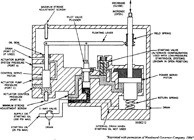
Refer to figure 9-5 for a schematic diagram of the
more than the compensation oil pressure during a
hydraulic amplifier. The control ports are connected to
transient. The variations in control oil pressure causes
correspondingly identified ports in the EG-R actuator
the control piston to move.
(fig. 9-4). Oil at these ports perform the following:
The control servo piston is connected to one end of
1. Port A- Actuator buffer compensation system
a floating lever in the amplifier. Any change in position
pressure always tends to move the amplifier
of the control piston is transmitted to the floating lever.
control servo piston downward (decrease fuel or
The movement of the floating lever is transmitted to the
steam).
Figure 9-5.--Hydraulic amplifier schematic diagram.
9-8

