
Table 9-1.--EG-M Electrohydraulic Governor Characteristics
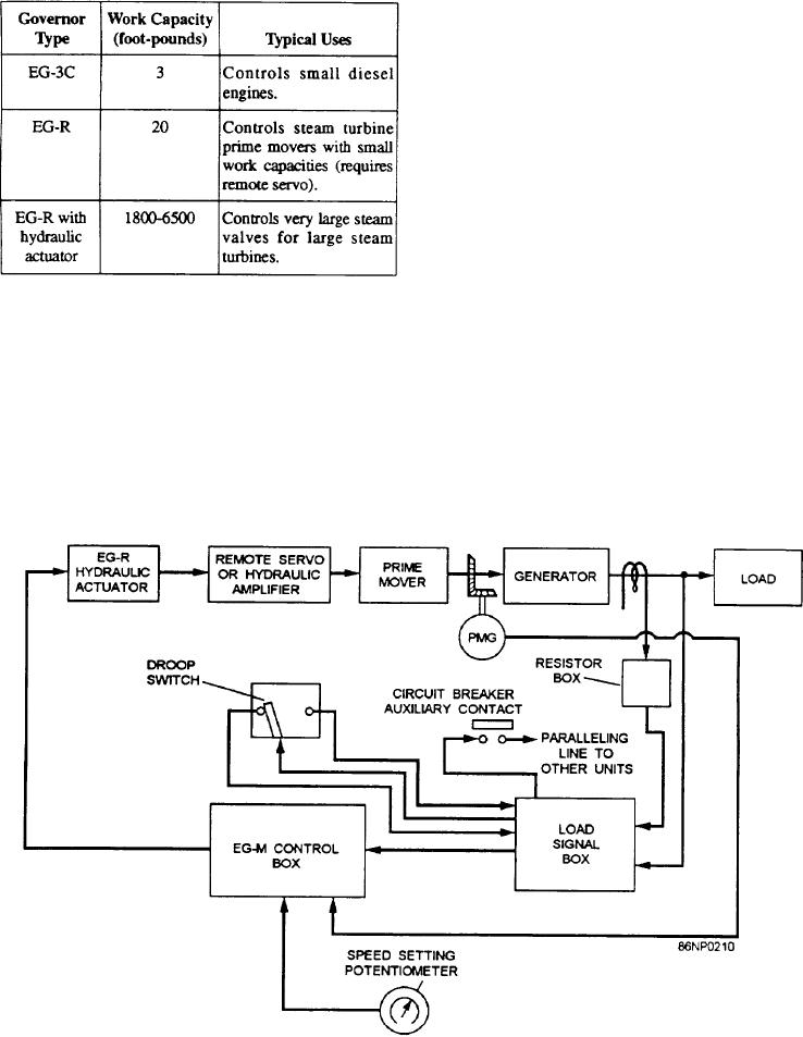
permanent magnet generator and is applied to the EG-M
control box. The control box compares this voltage with
a reference voltage. If there is a difference, it supplies
art output voltage that energizes the EG-R hydraulic
actuator. A pilot valve plunger in the actuator directs oil
from a remote servo. This increases or decreases the
steam that returns the turbine speed to normal.
The load signal box detects changes in load before
they appear as speed changes. It detects these changes
through the resistor box that develops a voltage from the
secondary of the current transformers. This voltage is
compared with the generator load output voltage. If a
difference exists, the load signal box applies a
proportional voltage to the control box.
The droop switch allows parallel operation of prime
use of the EG-3C, the EG-R, a hydraulic amplifier, and
movers with similar governors, dissimilar governors, or
with an infinite bus (shore power). The circuit breaker
the EG-R hydraulic actuator. The characteristics of
these governors are shown in table 9-1.
provides a path for control load signals to other
paralleled units.
OPERATION
EG-R Hydraulic Actuator
Look at the block diagram of figure 9-3. It shows
the use of the EG-R actuator with a remote servo. The
The EG-R hydraulic governor will be considered
input signal (voltage) is proportional to the speed of a
next. Figure 9-4 shows a schematic arrangement of this
Figure 9-3.--Electrohydraulic load-sensing governor system, block diagram.
9-4