governor. You can see that in this application the EG-R
hydraulic actuator is coupled with a remote servo
piston. High-pressure lines provide the means of
connecting the actuator to the remote servo. Oil from
an external source enters the suction side of the oil
pump. The pump gears carry the oil to the pressure
side of the pump. This fills the oil passages and
then increases the hydraulic pressure. When the
pressure becomes great enough, the relief valve
spring force is overcome, and the relief valve
plunger is pushed down. This uncovers the
bypass hole and allows oil to recirculate through the
pump.
The linear movement of the power piston in the
remote servo, used in conjunction with the EG-R
actuator, moves the engine or turbine linkage to
increase or decrease the prime mover speed. The
EG-R actuator controls the flow of pressure oil
to or from the servo piston. Pressure oil from the
pump is supplied directly to one end of the buffer
piston. The other end on the buffer piston connects
to the underside of the servo piston. Pressure in
this hydraulic circuit always tends to move the
power piston up in the decrease fuel direction.
The power piston cannot move up unless the oil
trapped on top of the power piston is allowed to drain.
It is drained to the sump by raising the pilot valve
plunger.
When starting the prime mover, manual control of
the speed of the prime mover is necessary until an
input signal and power becomes available to the control
box.
A drive force is necessary to rotate the actuator
pump gears and provide a relative rotation
between the nonrotating pilot valve plunger and its
rotating bushing. Upon loss of the electrical
signal, the EG-R and EG-3C hydraulic actuator
can go to shutdown. This depends upon design
application.
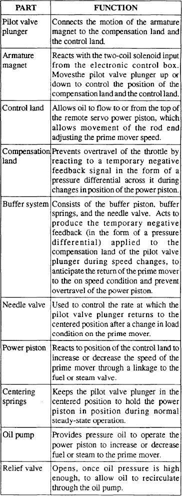
The major parts of the EG-R actuator (fig. 9-4)
and their functions are shown in the following
table:
9-6

