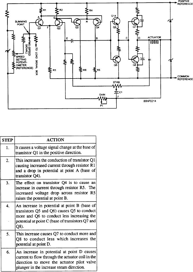
Figure 9-7.--EC-M control box, simplified schematic.
This steam increase causes the turbine to increase
If the speed-setting potentiometer is adjusted to
speed. The negative speed signal increase counteracts
increase speed, the following actions will occur:
the previous positive speed signal increase. A new
steady-state condition of essentially zero voltage is then
reached both at the summing point and the actuator.
To further explain the function of the amplifier and
its stabilizing feedback network, refer to the voltage
waveforms of figure 9-8 as well as the schematic of
figure 9-7.
Assume that a step input voltage signal is applied to
the summing point of the amplifier, as shown on curve
1 (fig. 9-8). If the feedback circuit is disconnected at
point I (fig. 9-7), the output voltage for this condition
(without feedback and stabilization) will be very high.
This is shown in curve 2 (fig. 9-8). This will cause the
turbine to hunt excessively. The gain (output voltage
divided by input voltage) is very high in this condition.
Assume that the feedback network is reconnected at
point I, and the stabilizing network is disconnected at
point J. In this case the output signal from point D is fed
through the stability potentiometer to the base of
transistor Q2 (point E). This reduces the amplifier gain.
In response to the step input of curve 1, an output voltage
for this condition (feedback connected but without
stabilization) is obtained (curve 3, fig. 9-8).
Earlier, we stated that the output voltage at point D
and at the actuator increases in response to an increased
positive potential at the summing point of the amplifiers,
9-11

