
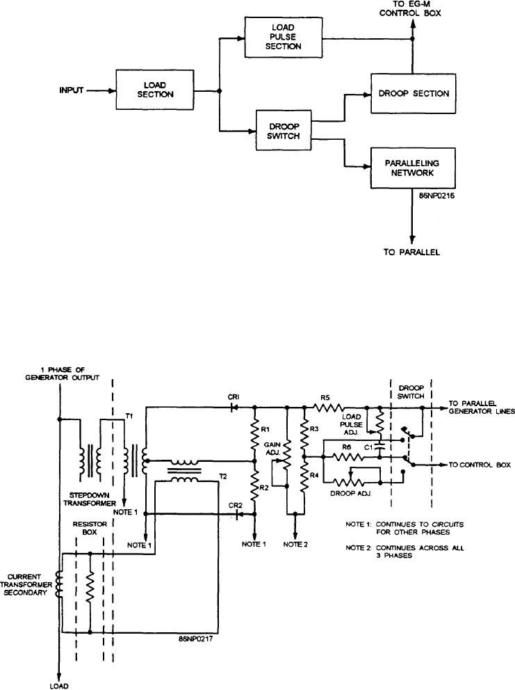
Figure 9-9.--Load signal box, block diagram.
to the generator load will be rectified by CR1 and CR2.
The amplitude of the signal can be varied by the
Although only one phase is shown in figure 9-10, each
GAIN ADJ. potentiometer. A variable pulse output is
phase is compared. The comparison circuitry is
developed by the charge/discharge time of C1 through
identical to that shown.
the LOAD PULSE ADJ. potentiometer.
Figure 9-10.--Load signal box, simplified Schemstic.
9-13