At shutdown, spring force returns the plunger to the
In this low-pressure starting-oil system, the starting
valve minimizes the force acting on the closing side
closed position.
(bottom) of the power servo piston. Starting oil
pressure within the range of 25 to 30 psi (typical) cannot
EG-M Control Box
generate sufficient force on the opining side (top) of the
power piston to overcome the combined forces of low
oil pressure and return spring force on the closing side
The EG-M control box is designed to provide the
of the power servo piston.
control signal to the electrohydraulic transducer in the
hydraulic actuator.
In the shutdown position, the starting valve blocks
the flow of starting oil to the closing side of the power
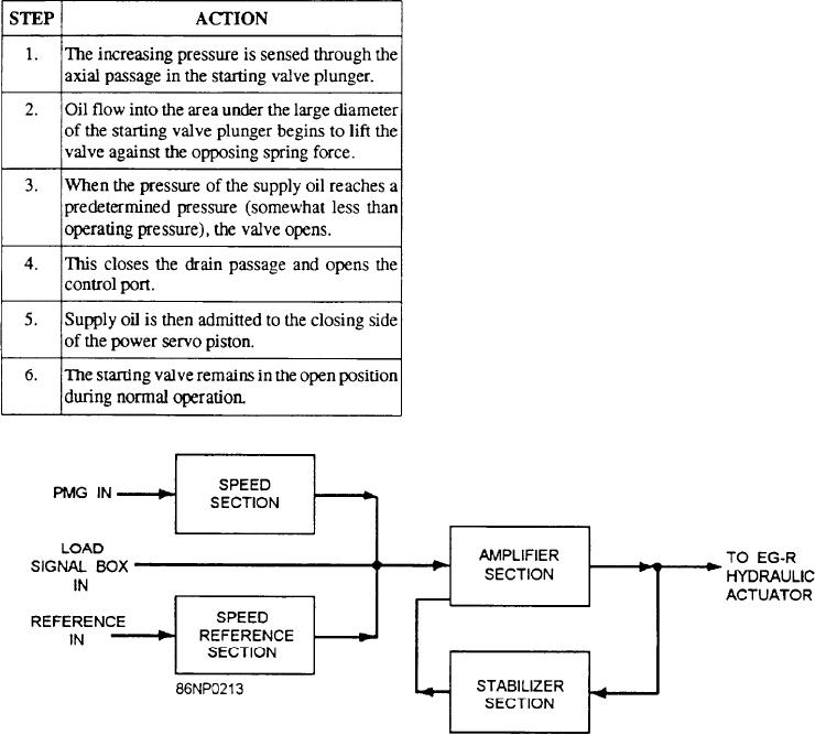
As shown in the block diagram of figure 9-6, the
piston. It also simultaneously opens the area to drain.
control box has three inputs. One is from the load signal
box and will be discussed later. The other two are from
When the prime mover starts and the normal supply
the PMG and the speed setting (reference)
pressure (prime mover oil pressure) becomes greater
potentiometer.
than the starting oil pressure, the following actions will
occur:
The input from the PMG is applied to the speed
section where it is converted into a negative dc voltage.
This voltage is proportional to the speed of the turbine.
The positive reference voltage (speed control) is
established by the speed-setting potentiometer but is
developed internally.
The outputs of the speed section and the speed
reference section are compared. If equal and of opposite
polarity, no signal is applied to the amplifier section. If
the speed of the turbine changes, there is a
corresponding change in the signal from the PMG. This
causes a change in the output of the speed section. An
error voltage is then applied to the amplifier section.
This is amplified and sent to the hydraulic actuator.
Some output is fed back through the stabilizer section
to keep the system from overreacting.
The schematic representation of the control box
(fig. 9-7) is a simplification of the actual amplifier and
is useful in describing its operation.
Figure 9-6.--EG-M control box, block diagram.
9-10

