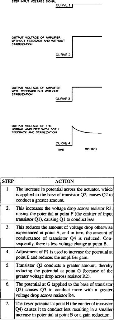
The stabilization signal is obtained through the use
of a capacitor. With capacitor C1 disconnected at
point J (fig. 9-7), the negative feedback effect
reduces the gain (curve 3, fig, 9-8). When the
circuit is reconnected at point J, the capacitor
temporarily diverts some of the feedback signal away
from point E during the charging period of the
capacitor.
In response to the input voltage (curve 1, fig. 9-8),
the initial output voltage of the amplifier goes to a high
level (curve 4, fig. 9-8) at the first instant the signal is
applied and the feedback signal is varied. As the
capacitor charges, the voltage comes down on the
curved portion of the line. It levels off at approximate] y
the same level as curve 3 when a steady-state condition
is reached. The shape of curve 4 is determined by an
RC time constant. R is adjustable by the stability
potentiometer. The normal response of the amplifier to
an open loop test (fig. 9-8) produces an output voltage
waveform characteristic of curve 4. This is in response
to the input voltage of curve 1.
Load Signal Box
The load signal box (fig. 9-9) enables the
Figure 9-8.--Voltage relationships.
governor system to respond to generator load
changes, as well as to speed changes. Load changes are
which causes the turbine speed to increase. Resetting of
detected and responded to before they appear as turbine
the amplifier is now achieved by the following actions:
speed changes. This minimizes speed change
transients.
The load signal box converts a three-phase input
signal (from the generator leads through the resistor
box) to a positive dc voltage. This voltage is
proportional to the kW load on the generator. The
voltage is applied to the load pulse section and the
paralleling network. When operated with dissimilar
governors, the droop and load pulse sections are used.
The droop switch determines the operating mode for
which the system is set up.
SINGLE GENERATOR OPERATION.-- Look
at the simplified schematic of the load signal box in
figure 9-10. Input signals for the load signal box are
taken from the secondary of the generator current
transformers and developed in the resistor box. The
resistor box contains three resistors (one for each phase).
The voltage input is applied to transformer T2 and
compared to the generator voltage phase. This is taken
from the generator line, stepped down, and applied to
transformer T1. If both voltages are in phase, they will
cancel. Therefore, no output will appear. If they are out
of phase (the load is changing), a voltage in proportion
9-12

