Home
Download PDF
Order CD-ROM
Order in Print
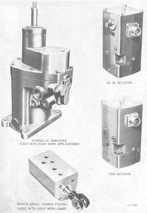
Figure 9-1.--Electrohydraulic load-sensing governor system components.
Figure 9-3.--Electrohydraulic load-sensing governor system, block diagram.
Electricians Mate
Page Navigation
360
361
362
363
364
365
366
367
368
369
370
Figure
9-2.--EG-M
electrohydraulic
systems.
9-3