
However, a motor generator or static converter will still
Load-measuring circuits are used in the
be required for type III voltage control.
electrohydraulic governor to obtain proper load sharing
on each paralleled generator. Most governing systems
NOTE: Refer to chapter 8 of this TRAMAN to
are designed so that any change in load produces a
identify the characteristics of type II and type III power.
signal that is fed into the electronic amplifier. This acts
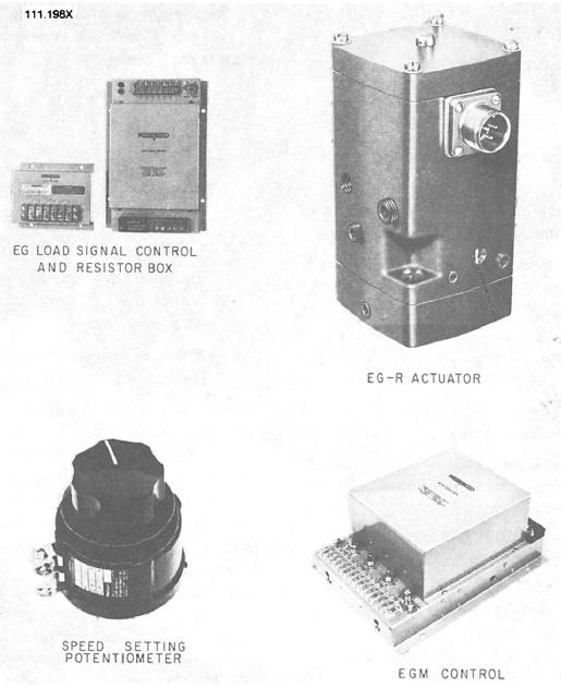
The electrohydraulic load-sensing governor used in
to offset any anticipated speed change caused by load
this chapter is made up of three separate assemblies (fig.
change. The load-measuring circuits of governors on all
9-1)--an EG-M control box, a speed-adjusting
generators that operate in parallel are connected by a
potentiometer, and a hydraulic actuator. Depending on
bus tie cable. The governor maybe designed or preset so
the control box and the type of service in which it is
that each paralleled generator will equally share the
used, a load signal box and a resistor box may be
total load. If not, a load-sharing adjustment must be
required
provided.
EGM SYSTEM
The steady state and transient frequency
The EG-M electrohydraulic governor system (fig. 9-
requirements for type II electrohydraulic governors
2) offers diversified work capabilities. Large or small
power can be met with of the type just described.
prime mover governor requirements can be met by the
Figure 9-1.--Electrohydraulic load-sensing governor system components.
9-2