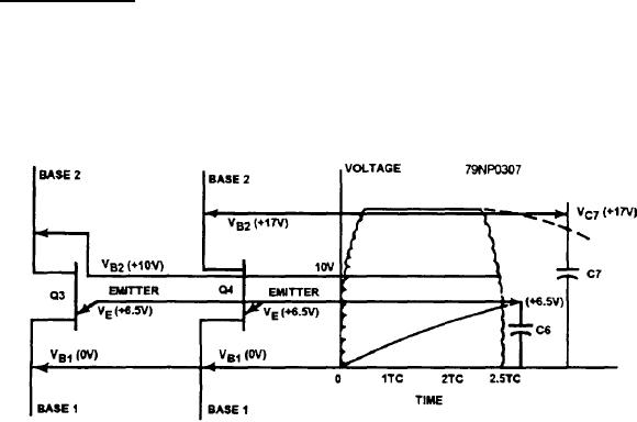
The voltage across Q3 and Q4 increases sharply
The 17 volts are applied across B1 and B2 of
and remains at 17 volts until the end of the cycle.
unijunction transistors Q3 and Q4. It is also
applied across capacitor C7 and across the RC
The 17 volts are applied across B1 and B2 of
circuit containing C6.
unijunction transistors Q3 and Q4, across
Capacitor C6 charges at the same rate as before
capacitor C7, and across the RC circuit
containing C6.
(assuming 10.3 volts in 4 time constants). The
period of time for this cycle is only 2.5 time
Capacitor C7 blocks rectifier CR14 and therefore
constants. Therefore, the voltage across C6 can
will maintain approximately 17 volts. The only
only reach approximately 6.5 volts within this
place C7 can discharge is through Q4, which has
time.
a very low leakage rate.
At the end of 2.5 time constants, approximately 17
The RC circuit containing C6 is charging at a
volts are held across Q4 by capacitor C7, with a sharp
specific rate. If we assume that within 4 time constants
decrease of voltage across B1 and B2 of Q3. When the
C6 reaches 10.2 volts, then the following events will
voltage reaches approximately 10 volts, Q3 can fire
occur:
because of its relative value of this voltage. Q4 still has
approximately 17 volts across it.
The VE for Q4 will fire before Q3.
After Q3 fires and the beat frequency goes to zero,
When Q4 fires, a voltage pulse is generated
the time process again repeats itself.
across R15 (fig. 8-34) and is applied to the gate
of SCR1.
You can see that different beat frequencies are
compared just as the differences were in phase and
SCR1 is then turned on.
voltage. The function of the frequency difference
When SCR1 turns on, transistor Q2 in the output
circuit is to energize relay K1 through the control of
circuit is supplied with a base current through
transistor Q2, if the difference of the frequency of the
limiting resistor R16.
bus and the oncoming generator is less than 0.2 Hz.
This turns on Q2. When the beat frequency
VOLTAGE DIFFERENCE MONITORING
voltage goes to zero, SCR1 turns off.
CIRCUIT
The timing process then repeats itself.
In the second example (fig. 8-38), there is a
The voltage difference monitoring circuit (fig. 8-39)
difference of 4.0 Hz in the beat frequency voltage. This
prevents energizing of the K1 relay if the voltage
causes a time period of half the previous example.
difference between the bus and the oncoming generator
Within this period of 2.5 time constants, the following
is more than 5 percent. The circuit does this by doing
events occur:
the following:
The voltage across Q3 and Q4 increases sharply
Reducing and rectifying both input voltages (bus
and remains at 17 volts until the end of the cycle,
and incoming generator)
Figure 8-38.--Firing sequence for Q3.
8-42

