Home
Download PDF
Order CD-ROM
Order in Print
PHASE DIFFERENCE MONITORING CIRCUIT
Figure 8-32.--Input voltage to CR10 (180 out of phase).
Electricians Mate
Page Navigation
351
352
353
354
355
356
357
358
359
360
361
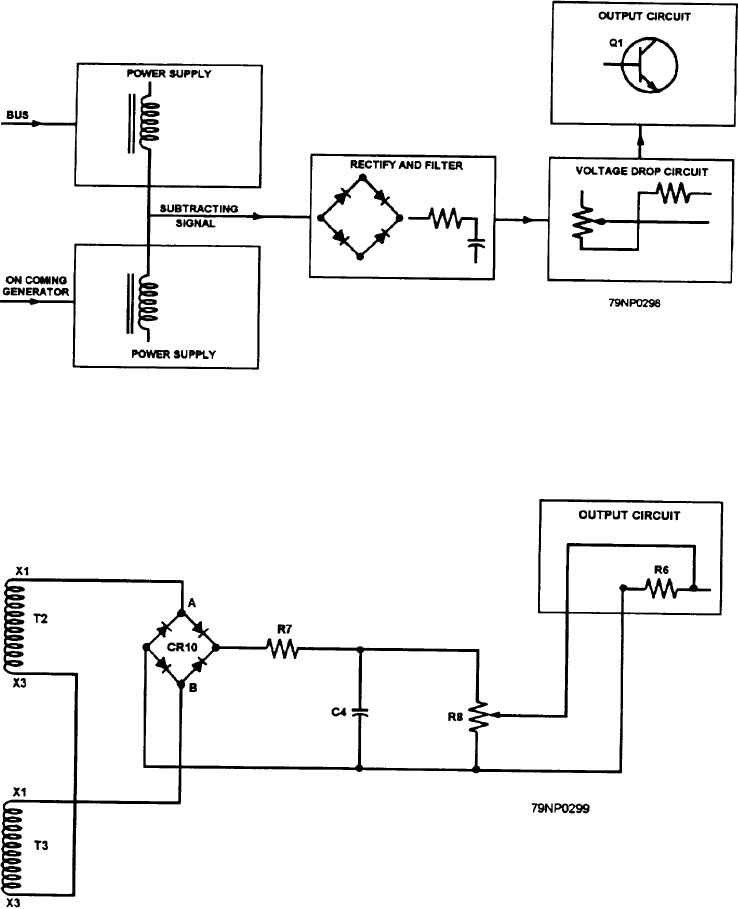
Figure
8-29.--Block
diagram
of
phase
difference
monitoring
circuit.
Figure
8-30.--Schematic
diagram
of a
phase
differnce
monitoring
circuit.
8-38