
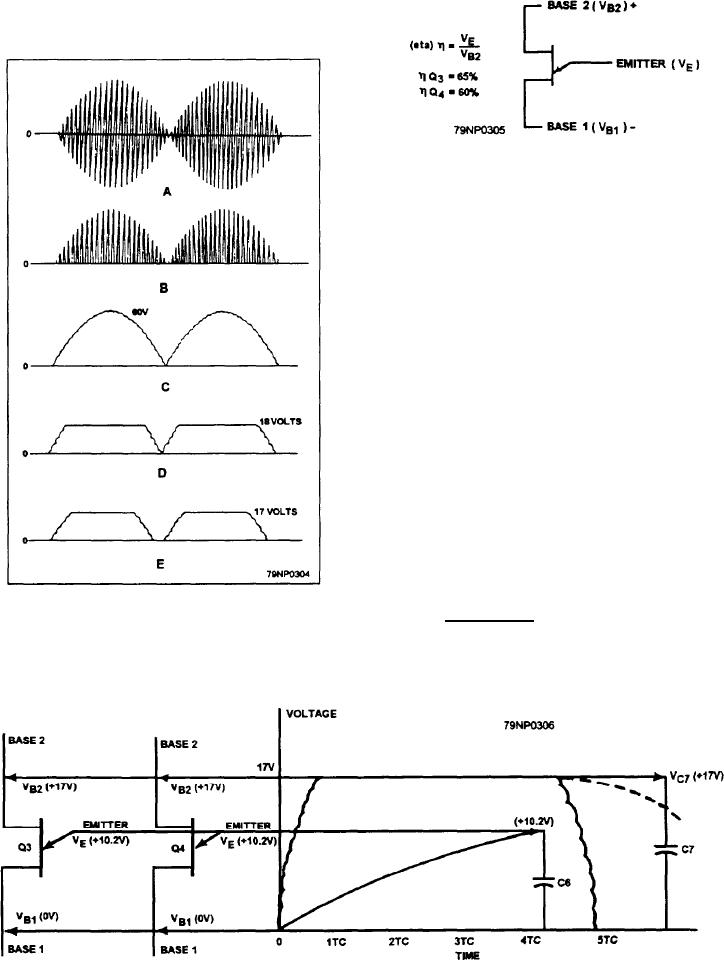
Figure 8-36.--Unijunction transistor.
Before continuing with the circuit description, you
need a brief explanation of the operation of a unijunction
transistor (fig. 8-36). A unijunction transistor has two
bases, B1 and B2, and one emitter. When the voltage
between B1 and the emitter rise to a certain percentage
of the voltage between B1 and B2, the unijunction
transistor will fire, The percentage is equal to emitter
voltage divided by the B2 voltage. In the case of the
unijunction transistors, it is equal to a nominal 62
percent. This means that when the emitter voltage is
approximately 60 percent of B2 voltage, both in
reference to B1, the unijunction transistor will fire. By
knowing that (1) Q3 and Q4 have different values for
the same voltage, (2) C6 has a definite charging rate
(determined by R9, R10, R13, and rectifier CR14), and
(3) that different beat frequencies have different time
intervals, you should have a basic understanding of how
the timing circuit operates.
In the following examples of how unijunction
transistors are find, the values used are arbitrary.
In the first example, (fig. 8-37), there is a difference
of 0.2 Hz in the beat frequency voltage. This causes a
time period of 5 time constants for 1 cycle. Within the
Figure 8-35.--Beat frequency voltages.
5 time constant period, the following events will occur:
Figure 8-37.--Firing sequence for Q4.
8-41