Phase Control Circuit
The phase control circuit (fig. 8-24) contains
components and circuits (similar to those in the
oscillator circuit) that function to control the firing of
the SCRs in the teaser (secondary) inverter and maintain
the proper phase relationship between the outputs of the
two inverters.
Voltage Regulators
The voltage regulator circuits (fig. 8-24) regulate
the converter output voltage by controlling the firing
time of the main SCRs in each inverter. The output of
a transformer connected across the converter output is
rectified to produce a dc signal that is proportional to the
converter output voltage. This signal is filtered and
compared in a Zener reference bridge to produce an
error signal output when the converter output voltage
varies from normal. This error signal is used to fire the
inverter control SCRs, which in turn, control the firing
time of the main SCRs.
Control Power Supplies
The converter (fig. 8-24) contains two control
power supplies (one for each inverter), which supply
regulated +30 volts dc to the various converter circuits.
The input to the power supply transformer is taken from
the 450-volt ac line. The power transformer output is
rectified by a full wave bridge rectifier and regulated by
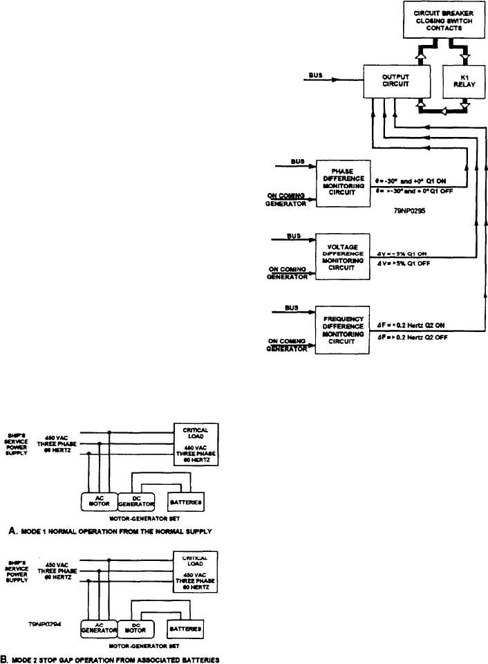
Figure 8-26.--Block diagram of synchronizing monitor.
a Zener diode regulator to produce the +30 volt dc
output.
NO-BREAK POWER SUPPLY SYSTEM
A no-break power supply system (fig. 8-25) is
designed to provide an uninterruptible electrical power
supply that is relatively constant in voltage and
frequency under all load conditions. The no-break
supply automatically takes over the power supply to a
load when the normal supply is interrupted by a change
infrequency or voltage. This type of system is required
by ships with equipment, control, or computer systems
that need an uninterrupted electrical power supply for
effective operations. It is presently being used with
ships using central operations systems.
The system uses an MG set, batteries, and
associated controls to provide its regulated output.
Either unit of the MG set can perform as a motor with
the other as a generator, thus permitting two modes of
operation.
MG MODE 1
In mode 1 operation of the MG set (fig. 8-25, view
A), the ac end of the set is being driven from the ship's
Figure 8-25.--No-break power supply, block diagram.
service power supply; and the dc end is a generator
8-34

