
30-KW MOTOR-GENERATOR SET
An additional output voltage compensation is
provided for cable loss when the stud of terminal Y2
passes through current transformer T5. It induces a
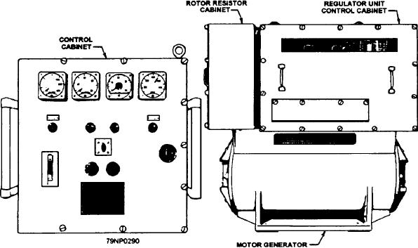
The closely regulated MG set (fig. 8-21) consists of
signal in T5 proportional to the load current.
a 450-volt, three-phase, 60-Hz, 50-hp, wound rotor
Adjustment of potentiometer R21 provides
induction motor driving a 450-volt, three-phase,
400 Hz, 30-kW generator. The set is regulated and
compensation in this circuit. The potentiometer setting
compensates for the resistance in cables from the
controlled by a voltage and frequency regulating system
(housed in the rotor resistor and regulator unit control
regulator to the load. Once set, it doesn't have to be
changed unless the cables (not the load) are changed.
cabinets) and a magnetic controller with associated push
buttons and switches (located in the control cabinet).
MAINTENANCE
The magnetic controller is a conventional size 3
across-the-line semiautomatic motor controller
Normally, voltage regulators require little
(starter). The voltage-regulating system functions to
preventive maintenance, other than that described on the
supply the proper field current to the generator so as to
MRCs. This is because the components are stable and
maintain the generator output voltage within plus or
nonwearing with no moving parts (other than two
minus one-half of 1 percent of rated output voltage for
potentiometers). However, you do need to make
all load conditions. The frequency-regulating system
frequent inspections for dust, dirt, and moisture
functions to control the speed of the drive motor to
accumulation. Also, you need to clean the equipment as
maintain the output frequency of the generator within
necessary.
plus or minus one-half of 1 percent of its rated value for
all load conditions. In addition, power-sensing
networks that function to eliminate speed droop with
CLOSELY REGULATED POWER
increased generator loads and to maintain equal sharing
SUPPLIES
of the load between paralleled generators are included.
Certain weapons, interior communications, and
Voltage Regulating System
other electronics systems aboard modem Navy ships
require closely regulated electrical power (type 111) for
The voltage regulating system consists of a voltage
proper operation. Special closely regulated
regulator and a static exciter, as shown in figure 8-22.
motor-generator (MG) sets supply the greater part of
The output from the power section of the regulator, in
this power. Static-type converters are also used in some
conjunction with windings within the static exciter,
installations.
Figure 8-21.--Motor-generator set with control equipment.
8-30