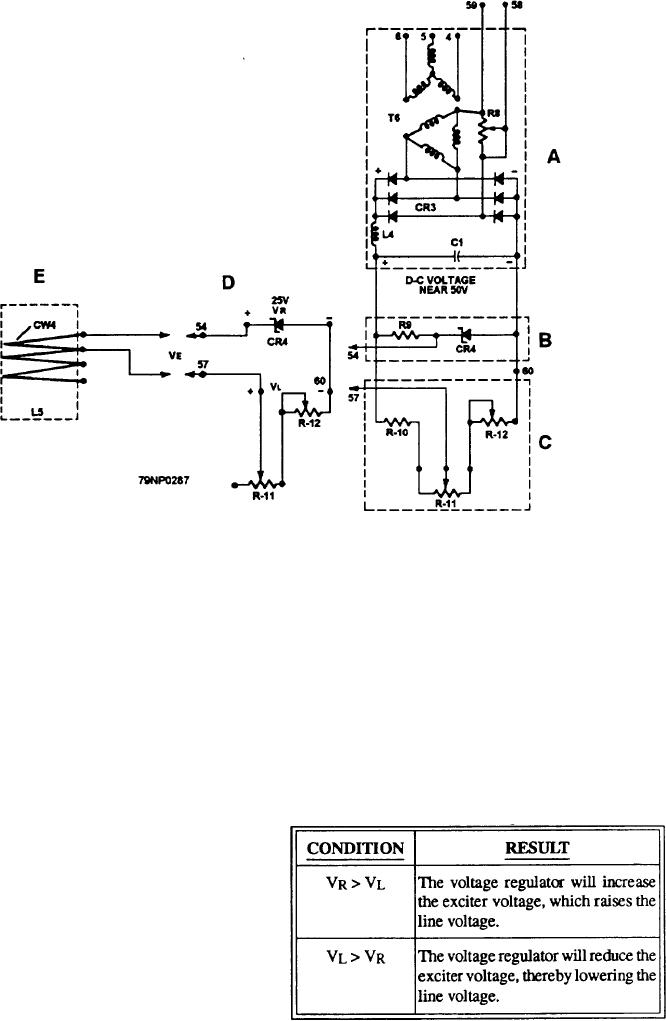
Figure 8-18.--Automatic voltage regulator.
4. Relocate the meter leads to measure line voltage
(numbered 54, 57, and 60) in figure 8-18, view C. These
VL and verify that it has the same value (25
tests reveal several facts that explain the ERROR
volts) as VR, when VE is zero.
VOLTAGE (VE) produced across terminals No. 54 and
his will be for this measurement only. If resistor
No. 57 (fig. 8-18, view D). To use the dc voltmeter, use
R11 is readjusted to produce, for example, either a 27-
the following procedure:
or a 23-volt reading for VL, then VE has a numerical
value of 2 volts. However, polarities are reversed.
Disregard meter-polarity connections since
The two conditions that may cause a change to the
some of the performance tests will cause the
excitation voltage by the automatic voltage regulator are
meter to read downscale when the polarity (of
given in table 8-4.
the error voltage) reverses.
Table 8-4.--Effects of Changes to VL and VR
2. Initial changes in the amount of VE are made by
adjusting the slider on VOLTAGE ADJUSTING
RHEOSTAT R11. A slider position of R11 will
be found where VE registers zero.
3. Then, reposition the meter leads to verify that
the reference voltage VR (terminal No. 60 is
negative; No. 54 is positive) will always remain
at 25 volts regardless of generator output.
8-25

