
which is not now required. Manual control of generator
MANUAL VOLTAGE CONTROL CIRCUIT.--
voltage is achieved by the manual control rheostat R7.
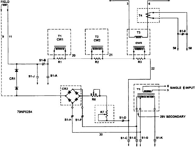
With switch S1 (fig. 8-15) in the manual position,
contacts F and H are closed, connecting the 29-volt
Varying the resistance of potentiometer R7
secondary of transformer T5 to the bridge rectifier CR2.
functions to vary the saturation of the cores of T1, T2,
The resulting dc signal flows in the following manner:
and T3. Varying the amount of dc alters the core
saturation. Those variations will change the voltage
1. From the negative terminal of CR2 through
value that is induced from each primary into its
resistor R6
associated secondary winding (8- 13).
2. Through the manual control rheostat R7,
3. Through closed switch S1-D to conductor No.
Automatic Voltage Regulator
22, and
The static exciter alone (fig. 8-13) will not maintain
4. Through the series arrangement of each SCPT
the different amounts of field current required to
control winding.
maintain a constant value of ac voltage at the generator
5. There, it combines temporarily with the flow of
terminals during various load changes. Therefore, a
the generator's dc field passing from the+ side
voltage regulator is needed to hold the generator voltage
to the side of rectifier CR1, and finally
constant.
6. It terminates at the positive terminal of rectifier
The automatic regulator controls the exciter output
CR2.
by precisely regulating the flow of dc in the control
winding of each SCPT (T1, T2, and T3 shown in figure
Five switch sections of S1 are closed to establish
8-16). Here, the initial ac is provided by the 85-volt
manual control for the exciter's output, namely, B, D, F,
secondary of transformer T5. This feeds rectifier CR6
H, and O. Switch S1-0 short circuits the output of
(through terminals 41 and 52) to provide the dc source
transformer T4 to eliminate a drooping characteristic,
Figure 8-15.--Manual voltage control circuits.
8-22