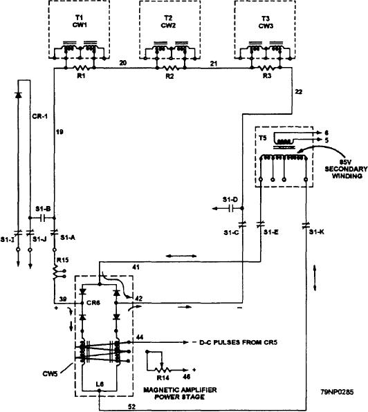
Figure 8-16.--Final-stage magnetic amplifier.
SENSING CIRCUIT.-- To obtain the best
at terminals 39 and 42. The flow of dc is precisely
regulation during unbalanced load conditions in the
controlled by the ohmic reactance values of each coil of
three phases, the regulator uses the sensing circuit (fig.
L6.
8-18, view A), which responds to the average of the three
The reactance of each coil of L6 is controlled by the
values of ac line voltages (terminals 4,5, and 6).
state of magnetic saturation produced by the regulated
Transformer T6 reduces the line voltage of each
dc flow from rectifier CR5 of the first stage magnetic
phase to a convenient value. Rectifier CR3 converts the
amplifier (fig. 8-17, view A). This regulated dc signal
three-phase ac to dc voltage. If an unbalanced condition
is transmitted to the control windings of the coils in L6
causes the three line voltages to become unequal, the dc
through terminals 5 and 6 of fig. 8-12, view A.
across the rectifier will have considerable (third
harmonic) ripple. However, the combined filter actions
The control of this regulated output of rectifier CR5
of inductor L4 and capacitor C1 will remove the ripple
originates with sampling the average of the three line
and produce dc across C1 (near 50 volts). This is always
voltages by the sensing circuit in figure 8-18, view A.
in proportion to the average of the three line voltages.
This voltage is processed further in the reference and
comparison circuits (fig. 8-18, views B and C) for
Resistor R8 is used for reactive droop compensation
and will be discussed later.
amplification in the preamplifier of figure 8-17.
8-23

