CW4 current changes so the core flux reaches saturation
MAGNETIC AMPLIFIER CIRCUITS.-- The
essential parts of the two stages of magnetic amplifiers
for part of the cycle, the gate-winding inductance
(figs. 5-16 and 5-17) consist of L5, L6, CR5, CR6, R13,
drops to a very low value for that part of the cycle. A
R14, and R15.
portion of the supply voltage wave is then applied to the
load.
Changes in generator voltage produce changes in
current in the comparison circuit. These are in the order
STABILIZING CIRCUIT.-- In any closed-loop
of milliamperes while flowing in the control winding,
regulating system that contains several time constants
CW4 (fig. 8-17). It is necessary to amplify these initial
and has high gain, sustained oscillations would be
small currents so their effect is in the order of several
produced. Undesired oscillation is sometimes called
amperes in the final control windings of CW1, CW2,
hunting. To prevent hunting, a stabilizing falter circuit
and CW3 of the SCPTs.
(resistor R17 and capacitor C3 in figure 8-12, view A)
Two magnetic-amplifier gates (GW1 and GW2 as
is used to remove the normal ripple from the exciter
shown in figure 8-17) function automatically and
output voltage. Another network (resistor R18 and
alternately to regulate the flow of ac delivered by the
capacitor C4) stabilizes the exciter output voltage.
56-volt secondary of transformer T5. The automatic
Nonlinear resistor R19 is used to suppress abnormally
regulation is achieved by saturating and&saturating the
high transient voltage that may appear across the field
flux in the cores of GW1 and GW2. The degree of flux
rectifier CR1.
at any moment in each core is determined by the
previously described conditions of dc flow in the control
REACTIVE DROOP COMPENSATION
winding, CW4.
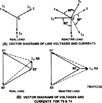
CIRCUIT.-- Current transformer T4 and resistor R8
are used to obtain the generator-drooping characteristic.
The flow of gated ac and its conversion into dc
The vector diagrams for this circuit are shown in figure
pulses in another control winding (CW5 of the power
amplifier L6), is readily traced by inspection of the
8-19, views A and B. Figure 8-19, view A shows the line
arrows in figure 8-17, views B and C. These arrows
voltages and currents for real and reactive loads. Figure
alongside the conductors and rectifier elements are in
8-19, view B shows the voltages on the secondary of the
the direction of electron flow during one half cycle in
transformer T6, along with the IR (voltage) drop
figure 8-17, view C. The control winding current can
(produced across resistor R8 because of its current from
be changed until the full supply voltage is applied to the
the secondary T4, called I4).
load In this way, a control winding in each stage of the
several saturated cores controls the output from the
magnetic amplifier.
The series resistors R14 (fig. 8-17) and R15 (fig.
8-16) are adjusted so each amplifier operates in the
center of its saturation curve.
Inductor L7 (fig. 8-17) is used to assure smooth
continuous control of the second-stage amplifier.
Transformer T5 is used to supply power to the two
magnetic amplifiers. It is also used to supply control
current when it is operating in manual control.
A control winding would function to change its flux
by means of either dc pulses or filtered dc. Control
winding CW4 employs filtered dc by using capacitor Cl
(fig. 8-18) in the sensing circuit.
If, in figure 8-17, view B, the supply voltage (from
transformer T5) is applied to the gate winding in series
with its CW5 load, most of the voltage drop is across the
gate winding (and very little voltage drop is across the
CW5 control-winding load), provided the flux in the L5
Figure 8-19.-- Vector diagrams of reactive droop circuit-
core never reaches saturation. If the control-winding
8-26

