
Figure 8-13.--Static exciter.
Perform the following procedure to start the system:
1. Place the control switch (S1) in either the
MANUAL or AUTOMATIC position.
2. Move the spring-return field-flashing switch S-2
(fig. 8-12, view C) to the FLASH position. This
allows flashing current to flow temporarily to
the field of the ac generator, as shown in figure
8-14, when the prime mover is started and the
generator is brought up toward its rated speed.
3. Remove switch S2 as soon as the generator
voltage begins to build up. This is because
thereafter the static exciter is capable of
continuing the dc voltage required by the
generator field.
The field does not have to be flashed every time the
system is placed in operation. It is usually necessary to
flash the field only after a generator malfunction or
when the generator is idle for long periods of time, such
as overhaul periods.
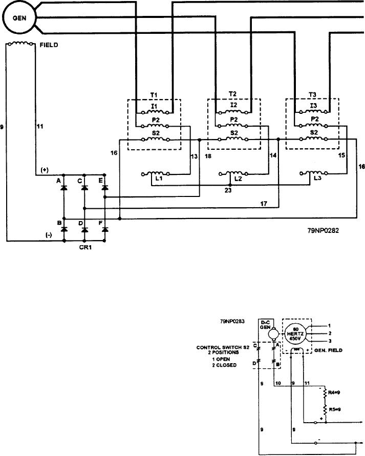
Figure 8-14.--Field-flashing circuit.
8-21