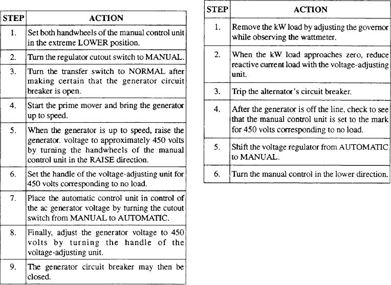
The normal operational sequence for placing a
Table 8-3 gives the procedure to remove an
alternator from the line.
single generator on the line is as shown in table 8-2.
Table 8-3.--Removing an Alternator From the Line
Table 8-2.--Normal Operating Sequence for Starting One
Generator
Maintenance
Maintenance instructions for a specific rotary
amplifier regulator given in the MRC and 3-M
instructions take precedence over other procedures.
However, the articles concerning care of rotating
electrical machinery in chapter 310 of the NSTM should
be observed in all cases where they do not conflict with
the MRC, 3-M, or manufacturer's instructions.
The amplidyne's short-circuiting brushes should be
If the generator is to be operated in parallel with a
checked periodically. Improper brush contact may
generator already connected to the bus, close the circuit
result in an excessively high amplidyne voltage output.
breaker of the incoming generator only when the two
voltages are synchronized. As soon as the two
STATIC EXCITATION AND VOLTAGE
generators are operating in parallel, readjust the
REGULATION SYSTEM
governors of the prime movers until each unit takes its
share of the kW load. Then equalize the power factors
The static excitation voltage regulator system
of the machines by means of the voltage-adjusting units.
furnishes ac generator field current by rectifying a part
When the kW loads and power factors on the generators
of the ac generator output. After the ac generator has
are equal, the current of each generator should then be
built up some output with the aid of a field-flashing
equal.
power source, an automatic voltage regulator controls
the output of a static exciter to supply the necessary field
If the system voltage is high after the power factors
current.
are balanced, slowly turn the voltage-adjusting units of
both generators in the lower direction. Turn it until the
The schematic of a static excitation and magnetic
system voltage is approximate y 450 volts. If the system
amplifier-type voltage regulator system is illustrated in
voltage is low, slowly turn the voltage-adjusting unit of
figure 8-12. The system provides field excitation in
both generators in the raise direction until the system
either manual or automatic control for the 400-kW,
450-volt, three-phase, 60-Hz generator.
voltage is approximately 450 volts.
8-18

