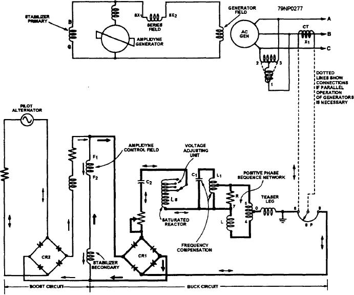
Figure 8-8.--Automatic control circuit.
in such a direction (from F1 to F2) that the amplidyne
voltages of the generator. Also, a frequency-
will boost the ac generator voltage. The saturated
compensating network permits the regulator to hold the
reactor circuit tries to force current through the control
ac generator voltage practically constant between 57
field in the opposite direction (from F2 to F1). This
and 63 Hz.
tends to decrease the generator voltage. When the ac
A schematic diagram of the automatic control
generator voltage is near normal, the regulator is at its
circuit is shown in figure 8-8. The circuit consists of a
normal operating point. The boost current supplied by
buck circuit, shown in heavy lines, and a boost circuit,
the pilot alternator is in the opposite direction. It is
shown in light lines. The ac portions of the circuit are
nearly equal to the buck current supplied by the
indicated by double-headed arrows. The dc portions are
saturated reactor circuit. Thus, the current through the
represented by single-headed arrows. The saturated
control field is negligible. The amplidyne excitation is
reactor, Ls, is energized by the ac generator voltage that
provided by the series field of the amplidyne to maintain
is to be regulated. It is connected to rectifier CR1. The
normal terminal voltage of the ac generator.
pilot alternator feeds rectifier CR2. The amplidyne
If the generator voltage should drop slightly
control field, F1 and F2, is connected across the output
below normal, the buck current supplied by the
of CR1 and CR2. The amplidyne exciter supplies the
saturated reactor would drop, considerably. This action
ac generator field directly.
causes a boost current to flow in the control field, which
The voltage from the pilot alternator tries to force
tends to raise the ac generated voltage and prevents a
further decrease in the terminal voltage.
current through the amplidyne control field. It does this
8-13

