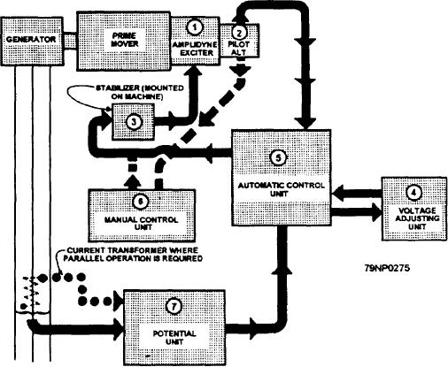
In the GEN A position, the standby regulator has
1. An amplidyne exciter (1)
taken control from the normal regulator of generator A.
2. A pilot alternator (2)
Generator B is connected to its normal regulator.
3. A stabilizer (3)
In the GEN B position, the standby regulator has
4. A voltage-adjusting unit (4)
taken control from the normal regulator of generator B.
Generator A is connected to its normal regulator.
5. An automatic control unit (5)
6. A manual control unit (6)
Amplidyne Exciter
7. A potential unit (7)
The amplidyne exciter (fig. 8-6) is a rotary amplifier
This is illustrated by the block diagram in figure 8-6.
that responds quickly to small changes in control field
Some installations include two normal voltage
current to cause large changes in output. It is mounted
regulators and one standby regulator for two ac
on the shaft of the prime mover. It provides the
generators.
excitation for the ac generator.
A cutout switch with two positions (manual and
automatic) is provided for each generator. The cutout
Pilot Alternator
switch is used to connect the amplidyne exciter and the
regulator for either manual or automatic control of the
A voltage regulator requires a "reference" or
ac generator voltage.
standard to which the voltage being regulated may be
compared. This determines whether or not the regulator
A transfer switch with three positions (NORMAL,
should act to change the excitation of the ac generator,
GEN A, and GEN B) is also provided. The transfer
In a direct-acting voltage regulator, discussed above, the
switch permits substituting the standby voltage
reference is provided by a coiled spring. In the
regulator for either of the two normal regulators.
amplidyne voltage regulator, the reference is provided
In the NORMAL position, generators A and B are
by a "boost" current. Ths current is approximately 0.5
connected in the normal automatic voltage control
ampere from the pilot alternator. The pilot alternator
(fig. 8-6) is a small permanent-magnet, single-phase ac
circuits of their respective regulators. The standby
regulator is disconnected.
generator, mounted on an extension of the amplidyne
Figure 8-6.--Block diagram of an amplidyne voltage regulator system.
8-11

