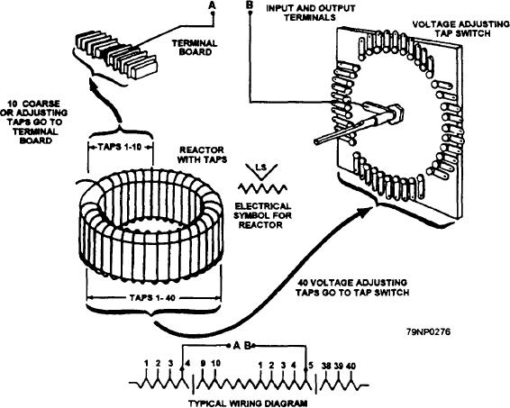
panel. The saturated reactor is the main component of
shaft. The effective voltage output of the pilot alternator
the voltage-adjusting unit. It is the heart of the regulator
is essentially constant.
system.
Stabilizer
The saturated reactor determines the ac generator
voltage that the regulator will maintain. It consists of a
The stabilizer (fig. 8-6) is mounted on or near the
tapped coil of approximately 400 turns wound on a soft
amplidyne exciter. It prevents sustained oscillations in
iron core. The core is operated in the saturated region
generator output. It is essentially a transformer.
so that a very small change in the applied voltage and
However, because it is in a de circuit, the stabilizer
flux density will produce a large change in coil current.
functions only when there is a change in the exciter
voltage. The secondary winding is connected in series
Changing the taps on the coil changes the reactance
with the control field of the amplidyne exciter.
of the coil circuit. It also changes the voltage level held
by the regulator. Increasing the turns (to a higher tap
When the regulator operates to change the exciter
number) increases the reactance and voltage required to
voltage, a voltage is induced in the control field circuit
maintain a given coil current. Conversely, decreasing
through the stabilizer. This momentarily affects the
the turns decreases the reactance and voltage required
control field current to restrain the regulator from
to maintain the current. Tap changing is done only
making excessive correction of the exciter voltage. This
during original installation or an overhaul.
prevents hunting.
Automatic Control Unit
Voltage-Adjusting Unit
The automatic ccontrol unit (fig. 8-8) has the static
The voltage-adjusting unit provides ac generator
elements that are required for automatic voltage control.
voltage that the regulator will maintain. This unit (fig.
It is mounted inside the generator control switchboard.
8-7) consists of a tap switch and a tapped saturated
Portions of the control-unit circuit make the voltage
reactor. It mounts directly behind the generator control
regulator responsive to the average of the three-phase
panel. The handle of the tap switch is on the front of the
Figure 8-7.--Voltage-adjusting unit.
8-12

