Assume an instantaneous unbalance occurs with
the regulators for generators A and B, respectively, will
then be equal to each other.
generator A having a weaker field than generator B.
This unbalance can be caused by slight differences in
The regulator attempts to hold voltage Vr constant.
the reactance or saturation characteristics of the
Voltage, 7-8, depends on the value and phase angle of
generators or in the characteristics of the regulators.
the compensating voltage, 6-8. The network voltage,
Because the excitation is unbalanced, there is a
7-6, which is the difference between Vr and 6-8 and is
circulating current between the two generators. Their
proportional to the line voltage, has decreased slightly
power factors are therefore unbalanced.
because of this change. Thus, the line voltage will be
slightly less than that maintained before any change
The effect of this unbalance distorts the voltage
occurred to the system. This drop in line voltage
triangle, 7-6-8 (fig. 8-9, view C). The network voltage
resulted from the increase in reactive load current.
7-6, decreases slightly because of the drop in line
voltage. The compensating voltage, 6-8 (IbRp), from
Manual Control Circuit
the current transformer and the compensating rheostat
have changed. This is because of the unbalanced line
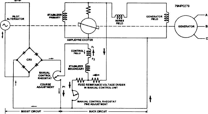
An elementary diagram of the manual control
currents and power factors. Therefore, the
circuit is illustrated in figure 8-10. The buck and boost
compensating voltage, 6-8, for generator B is greater
circuits are indicated by heavy and light arrows,
and at a different phase angle than the corresponding
respectively. The voltage that the amplidyne exciter
voltage for generator A. Thus, the resultant voltage, 7-8
will maintain across its terminals can be adjusted by the
(Vr), of the two machines is unequal and different from
manual control rheostats. Thus, the ac generator
the original voltage that the regulators were set to hold
terminal voltage can be varied. The manual control
constant .
circuit is so designed that for any one setting of the
manual control rheostat, the amplidyne terminal voltage
The regulators will act to change the excitation of
applied to the generator field will remain constant.
the two generators. This is done to restore the voltage,
7-8, to equal values of Vr for both regulators. They are
set by changing the values of the field currents so they
Operation
are balanced. The line currents and power factors will
then be approximately balanced to give equal
The schematic diagram of an amplidyne voltage
compensating voltages, 7-8. These voltages "seen" by
regulator installation is shown in figure 8-11.
Figure 8-10.--Manual control circuit.
8-16

