This action occurs because the pilot alternator is not
affected by the generator voltage and is still trying to
force a boost current through the control field
If the generator voltage increases slightly above
normal, the saturated reactor circuit would pass a large
additional current through the amplidyne control field.
This tends to buck or decrease the ac generated voltage
and prevents further increase in terminal voltage.
Manual Control Unit
The manual control unit (fig. 8-6) controls the
voltage of the generator when the automatic control
equipment is not in use. It consists of two resistor plates
and a single-phase, full-wave rectifier. The two resistor
plates are connected as a rheostat and a potentiometer,
which operate concentrically. The manual control unit
is mounted inside the switchboard. The operating
handwheels protrude through the front of the panel. The
large handwheel provides coarse voltage adjustment.
The small handwheel is used for fine or vernier
adjustment.
Potential Unit
The potential unit (fig. 8-6) provides signal voltage
to the regulator. This voltage is proportional to the
voltage of the ac generator. The unit has a potential
transformer and a potentiometer rheostat. The unit is
mounted inside the generator switchboard near the
current transformer and the generator circuit breaker.
The potential transformer is a special T-connected,
450-volt transformer. The potentiometer rheostat is
connected in the circuit of a current transformer. It is
used to provide the reactive load division between
generators operating in parallel.
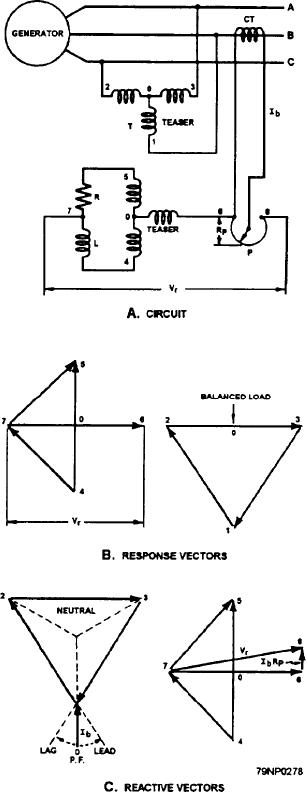
Three-Phase Response Circuit
The three-phase response circuit (fig. 8-9) consists
of the following components:
1. AT-connected potential transformer (T)
2. A resistor (R)
Figure 8-9.--Three-phase response circuit.
3. An inductor (L)
respectively (fig. 8-9, view B). The relationship of these
The resistance and inductance are in series across
voltages is 4-7-5, giving a resultant voltage, 7-0, in
one secondary winding of the potential transformer (fig.
phase with and added to the voltage 0-6.
8-9, view A). When a balanced three-phase voltage is
The resulting voltage, 7-0-6 (Vr), is the voltage of
impressed on the primary, 1-2-3, a voltage, 4-5-6,
the network used to energize the regulator circuits. The
appears across the secondary. The voltages across the
regulator at constant frequency will always act to
inductor, L, and the resistor, R, are 4-7 and 7-5,
8-14

