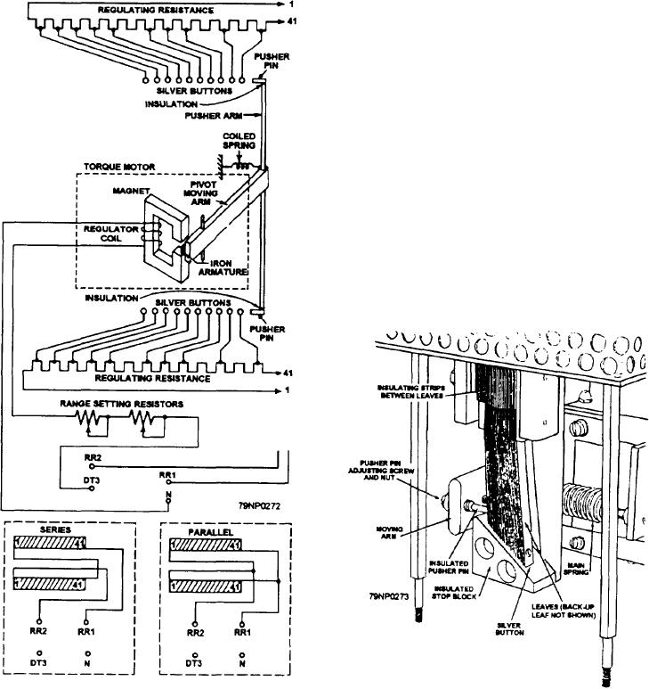
Control Element
a coiled spring are attached to the other end of the
moving arm. The pusher arm carries two insulated
pusher points arranged to bear against silver buttons.
The control element (fig. 8-3) consists of a regulator
These are spring mounted and connected to the
coil and a regulating resistance. The regulator coil is a
regulating resistance.
stationary coil wound on a C-shaped iron core with a
spring-mounted moving arm. The nonmagnetic
The silver buttons are individually mounted on leaf
spring-mounted moving arm is pivoted so that an iron
springs. They are insulated from each other. They are
armature attached to one end is centrally located in the
connected to consecutive taps on the stationary
fixed air gap of the magnetic circuit. A pusher arm and
regulating resistance plates (fig. 8-4). The resistance
plates consist of tapped resistance wire embedded in
vitreous enamel. The control element includes two
resistance plates. There is one for each silver button
assembly. They are mounted in the rear of the unit. The
silver buttons connect to taps from the associated
resistance plate.
The control element also includes two adjustable
range-setting resistors (fig. 8-3). They are connected in
series with the regulator coil. These resistors are used
to set the range (covered by the voltage-adjusting
rheostat) so that rated generator voltage is obtained with
the voltage-adjusting rheostat in the midposition.
The primaries of two potential transformers,
connected in open delta, are connected across the
terminals of the ac generator as shown in figure 8-2. The
secondaries of these transformers are connected to a
Figure 8-3.--Control element of a direct-acting voltage
regulator.
Figure 8-4.--Silver button assembly.
8-6

