
built into the regulator. It is connected in series with the
The installation of direct-fig (silverstat type)
shunt field of the exciter. The complete regulator
voltage regulators used on emergency ac generators is
includes
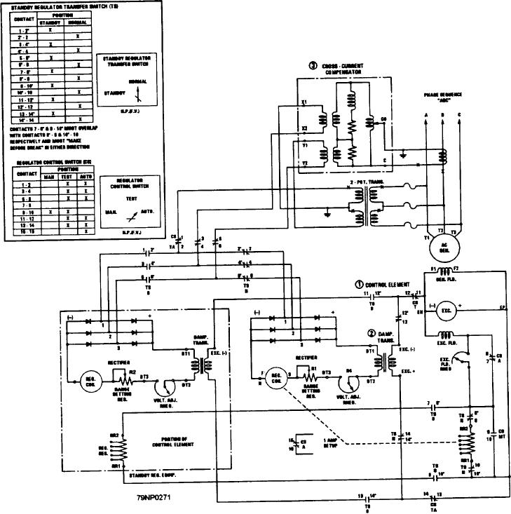
shown on the schematic diagram in figure 8-2. As you
have already learned, in each installation one regulator
1. a control element,
controls one ac generator. When a standby regulator is
2. a damping transformer, and
installed, a standby regulator transfer switch is also
installed. This allows for substituting of the standby
3. across-current compensator
regulator for the normal regulator.
The dc exciter in turn controls the voltage output of
the ac generator.
The voltage regulator controls the voltage of the dc
exciter by the variable regulating resistance. This is
Figure 8-2.--Schematic diagram of direct acting voltage regulator installation.
8-5