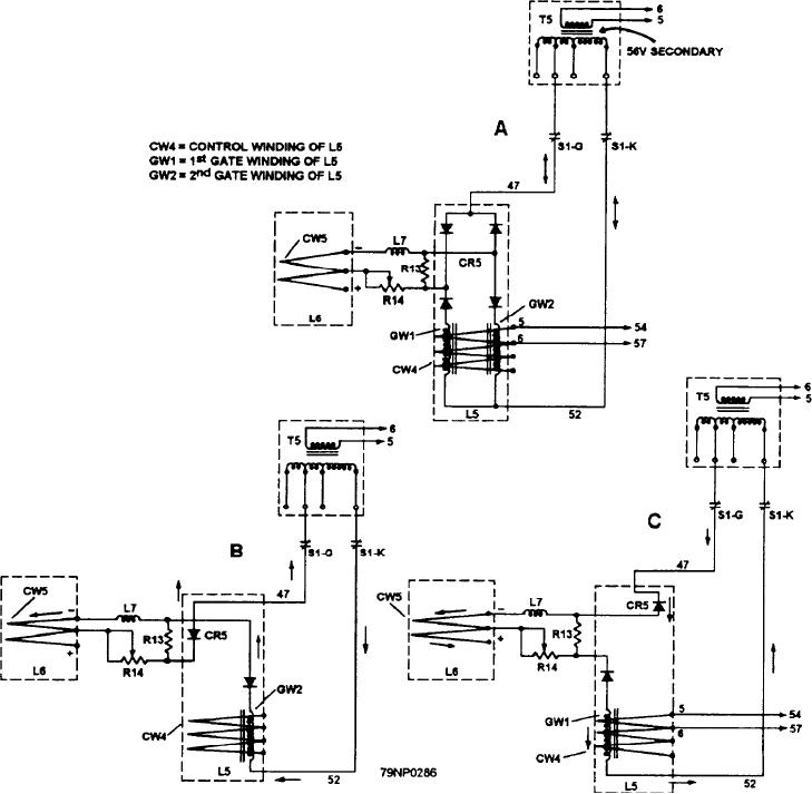
Figure 8-17.--First-stage magnetic amplifier.
REFERENCE CIRCUIT.-- The reference circuit
region and having nearly a constant 6.2 voltage drop
(fig. 8-18, view B) consists of resistor R9 and Zener
across each unit.
diode CR4. The function of CR4 is to supply a nearly
COMPARISON CIRCUIT.-- The comparison
constant (25 volt) reference voltage to the comparison
circuit consists of the reference circuit (fig. 8-18, view
circuit (fig. 8-18, view C). Dropping resistor R9 limits
B), combined with resistors R10, R11, and R12 (fig.
the current through CR4 to a safe value. If the voltage
8-18, view C). Its function is to compare the "average
(near 50 volts) across R9 and CR4 increases, the current
line voltage" to the reference voltage. It also acts on the
increases in both items. The voltage increases only
first-stage magnetic amplifier to correct any transients.
across R9, leaving the voltage across CR4 at its original
ERROR VOLTAGE.-- Three sets of tests are
voltage value (25 volts). CR4 consists of four Zener
made with a dc voltmeter at the three terminals
diodes with each diode operating in the breakdown
8-24

