5. Autotransformer control windings receive dc
The unit shown in figure 8-20 controls a single-phase
circuit. The input is at terminals X1 and X2 on terminal
current later in each half cycle and the potential
board 1 (TB1). Regulated output is from terminals Y1
at Y1 and 1 will decrease.
and Y2 on TB1. Regulation is achieved by controlling
If line potential at Y1 and 1 decreases too far, then
the two autotransformers, T1 and T2.
the following events will occur:
An acceptable waveform is ensured where one side
1. Q4 will conduct less and Q3 more.
of the transformer output goes to a harmonic filter via
terminal 1 on TB1. The filter consists of the inductor
2. Q2 will now conduct more and charge Cl faster.
L2 on TB6 and the parallel capacitors C6, C7, and C8.
3. Q1 will now fire earlier in each half cycle and
gate the SCRs earlier.
Voltage from terminals Y1 and 1 on TB1 drives the
rectifier bridge consisting of CR1, CR2, CR3, and CR4,
4. Control windings in the autotransformer receive
on the circuit board. This bridge provides dc power for
dc current earlier, decreasing autotransformer
the solid state components on the board
impedance and allowing line potential to
increase.
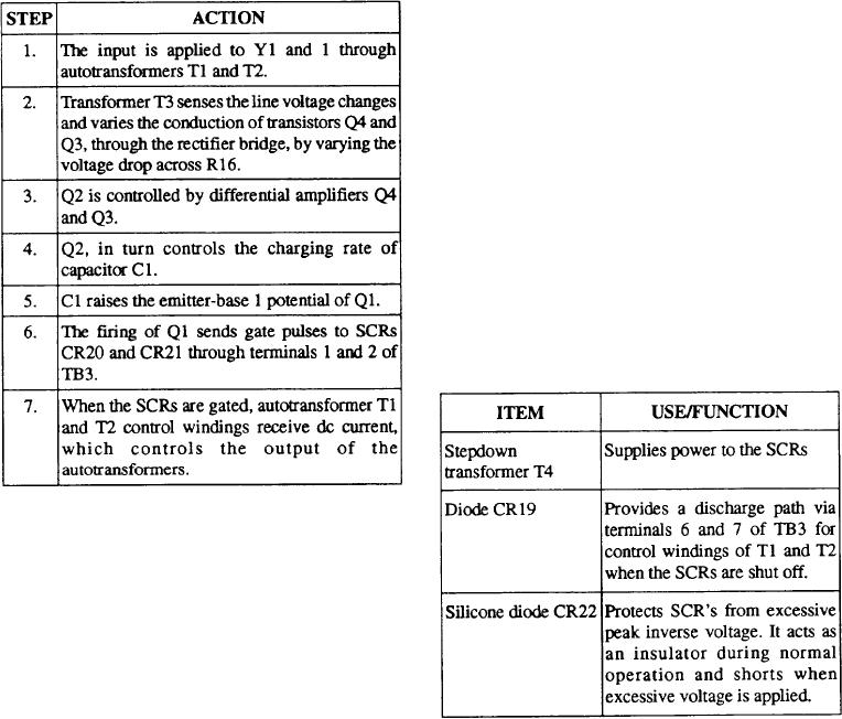
The operational sequence of the SPR-400 line
voltage regulator is shown in table 8-5.
Remember, the application of input power (across
terminals X1 and X2 of TB1, fig. 8-20) energizes the
Table 8-5.--Operation of the SPR-400 Line Voltage Regulator
two parallel operated autotransformers. The input
voltage is stepped up by an aiding winding (AID). This
is wound directly over the primary winding (PRI). The
voltage is then reduced to nominal output by an
opposing winding (OPP). The magnitude of induced
voltage in the opposing winding is varied by the level
of dc in the control windings (CON) from the SCRs.
The opposing and the control windings are separated
from the primary and the aiding windings by a magnetic
shunt. Increasing the dc in the control windings forces
the magnetic flux through the shunt. This decreases the
opposing voltage, and thus increases the output.
Items used to control the operation of the SCRs
(CR20 & CR21) in figure 8-20 are shown in table 8-6
below:
Table 84.--Description of Items Used in Controlling the
Operation of CR20 and CR21
For example, when line voltage increases, the
following events occur:
1. Q4 conducts more and Q3 conducts less.
2. Q2 in turn conducts less.
3. C1 will charge more slowly and Q1 will fire later
in each half cycle.
4. The SCRs will also be gated later in each half
cycle.
8-29

