
Transformer Rectifier
are connected in the wound-rotor circuit of the drive
motor.
The transformer rectifier unit (fig. 8-24) is an
Any change from the normal generator output
autotransformer and a three-phase, full-wave, bridge
frequency will cause the frequency-regulating system to
rectifier. The rectifier output is faltered and fed through
increase or decrease the rotor current, allowing the
choke coils to the static inverters. The choke coils limit
speed of the drive motor to compensate for the change.
the voltage appearing across the inverter SCRs.
constant by maintaining the speed of the directly
Oscillator Circuit
connected drive motor.
The oscillator circuit (fig. 8-24) provides the pulses
STATIC CONVERTER
for firing the SCRs in the main inverter. This circuit
consists of a unijunction transistor oscillator that
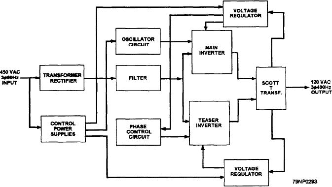
The static converter (fig. 8-23) converts 450-volt,
provides pulses at a rate of 800 per second. These pulses
three-phase, (50-Hz power to 120-volt, three-phase,
switch a bistable (flip flop) transistor multivibrator
400-Hz power for use as a shipboard closely regulated
circuit whose output supplies the primary of a
power supply. The converter automatically maintains
transformer. The transformer output (which is a square
the output voltage and frequency within plus or minus
wave) is amplified by a transistor push-pull circuit and
one-half of 1 percent of rated value for all load
fed to the primary of the oscillator output transformer.
conditions. This high degree of regulation is maintained
This transformer has a separate secondary winding for
even though the input voltage and frequency may vary
each main SCR in the main inverter. The output of these
as much as plus or minus 5 percent of rated value. The
secondary windings, fed through a differentiating circuit
450-volt, 60-Hz input is stepped dowm rectified, and fed
(which converts the square waves to pukes), is used to
to two static inverters. Each static inverter contains two
fire the SCRs. Each SCR being fired from a separate
main SCR groups consisting of two SCRs in series. The
secondary winding ensures simultaneous firing of the
inverter outputs are fed to Scott-connected transformers
SCRs in series. The phasing of the secondaries allows
firing of opposite SCRs at 180-degree intervals for
to produce the three-phase output. A simplified block
proper inverter action.
diagram of the converter is shown in figure 8-24.
Figure 8-24.--Static converter, simplified block diagram.
8-33