
YDRAULIC PUMP ASSEMBLY
Hydraulic fluid heaters in the oil reservoir will warm the
fluid up to 70F 5 degrees before use of the GSI
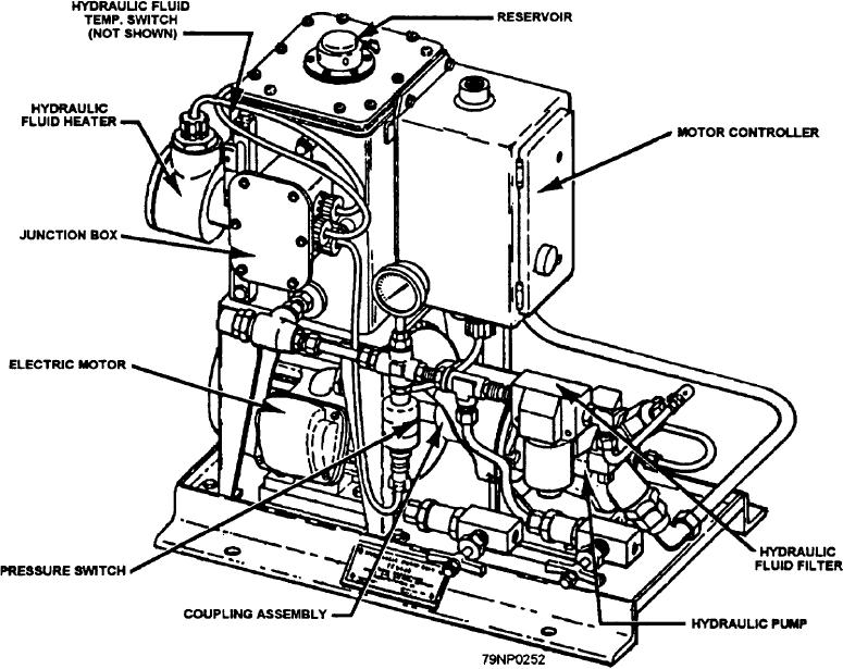
The hydraulic pump assembly (fig. 12-12) is located
system.
as close as possible to the stabilized platform. It
provides hydraulic fluid at 1,400 psi to the hydraulic
TRANSFORMER ASSEMBLY
actuator on the stabilized platform. `he motor and
controller operate on 440-V three phase received from
the ship's normal power supply. The temperature
The transformer assembly is located as close as
switches (not shown) operate the HIGH TEMP light on
possible to the stabilized platform. Its purpose is to step
the remote control panel. Also, a pressure switch in the
down the voltage for the source light (GSI) from 0- to
hydraulic pump discharge line will close at 1,200 psi. If
115- volts ac to 0- to 18.5-volts ac depending on the
not closed, the pressure switch will de-energize the
electronic panel assembly on low oil pressure.
setting of the intensity control.
Figure 12-12.--Hydraulic pump assembly.
12-9