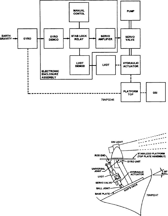
Figure 12-6.--Block diagram-stabilization circuits.
or roll, an error signal is developed by the synchro
transmitter stators in the gyro. Refer to the block
diagram in figure 12-6, and you can follow the path of
the error signal through the electronic enclosure
assembly. (The block diagram represents either the
pitch or the roll control loops since they are identical
electrically.) From the transmitter stators of the gyro,
the error signal is sent to the gyro demodulator where
the signal is changed born ac to dc The signal then goes
through a stabilization lock (stab lock) relay (described
later) and is amplified as it moves through the servo
amplifier which in turn operates the servo valve. The
servo valve opens and allows hydraulic fluid to enter the
hydraulic actuator (fig. 12-7). This levels the platform
and thus cancels the error signal. When this occurs, a
READY light is actuated on the remote control panel.
If the system develops a malfunction and the error signal
is not canceled, an error-sensing circuit will light the
NOT READY light on the remote control panel and turn
off the glide slope indicator.
In the previous paragraph you have learned the
Figure 12-7.--Stabilized platform assembly-functional
diagram.
normal mode of operation in the electronics portion of
the system. The stabilization lock feature (stab lock
12-5

