• Home
  • Download PDF
  • Order CD-ROM
  • Order in Print
Figure 12-9.--Stabilization control circuits--signal flow.
Figure 12-12.--Hydraulic pump assembly.

Electricians Mate
Page Navigation
  432    433    434    435    436  437  438    439    440    441    442  
img
Figure 12-11.--Remote control panel assembly.
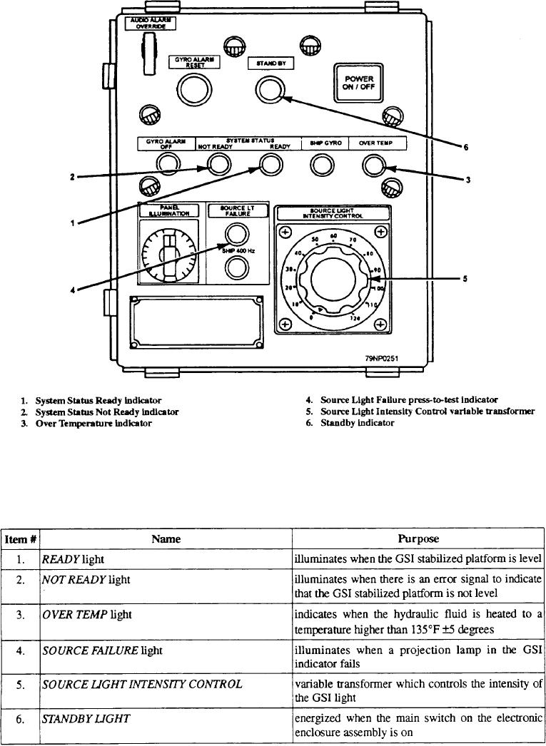
provides control and indicators for operating and
REMOTE CONTROL PANEL ASSEMBLY
monitoring the stabilized GSI from a remote location.
It contains- the following items.
The remote control panel (fig. 12-11) is located in
the helicopter control station (HCS). This panel
12-8


Privacy Statement
Press Release
Contact

© Copyright Integrated Publishing, Inc.. All Rights Reserved.