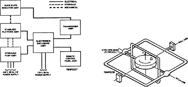
itself to the average pendulum position. Figure 12-18
block diagram in figure 12-16 shows the complete
shows the essential elements of the gyro.
system interconnected. The stabilized GSI system
cannot compensate for a ship's heave. Heave is the rise
GYRO ALARM CIRCUIT
and fall of the entire ship without a change in pitch or
roll angle.
The stabilized GSI system incorporates an
independent failure detection circuit. This detects any
VERTICAL GYROSCOPE
failure that results from a loss of stabilization. It does
this by comparing an input from the ship's gyro with the
The vertical gyroscope is basically a mechanical
output of the platform LVDT. When the system is
device. The essential element of the gyroscope is a
operating correctly in the internal gyro mode, the output
flywheel rotating at high angular velocity about an axis.
of the LVDT is directly proportional to the ship's
The flywheel is mounted within gimbals which allow it
motion. If the ship's motion from the LVDT is added out
2 degrees of freedom. (See fig. 12-17.)
of phase (reverse polarity) to the ship's motion from the
ship's gyro, the two will cancel. Any remaining voltage
When the gyroscope's flywheel is rotating at high
from the summation will be the error between the ship's
speed, its inertia is greatly increased. This causes the
gyro and the platform. The error is compared against a
flywheel to remain stationary within the gyro gimbal
preset limit, and if it exceeds this limit, the platform
structure. In order to align the gyroscope flywheel to
error relay is tripped. The gyro input is required for the
the local earth's gravity vector (downward pull of
alarm and is also used for the ship's gyro stabilization
gravity), a pendulum sensor is attached under the
and for the rate lead. The rate lead circuits are used to
spinning flywheel. In operation, the pendulum is held
reduce velocity lag of the platform and to increase
suspended within a magnetic sensor. The magnetic
system dynamic accuracy. In the ship's gyro
sensor measures the difference between the pendulum
stabilization mode, the system operates at a reduced
axis and the spin motor axis. The sensor output is
accuracy because of null errors and LVDT linearity
amplified and used to drive a torque motor. This motor
error. Therefore the ship's gyro mode is to be used as a
causes the gyro flywheel to rotate in a direction that
backup mode only.
reduces the sensor output. In actual operation, the
pendulum sensor is affected by lateral accelerations
HOMING BEACON
which cause it to oscillate about true position. To correct
for this oscillation, the gyro circuit's time constants are
The homing beacon is a high intensity white lamp
long. The long time constants cause the gyro flywheel
located on the mainmast or high on the superstructure.
to ignore periodic variations of the pendulum and align
It should be visible for at least 330 degrees in azimuth.
The beacon has a minimum effective intensity of 1,500
candles over a span of 7 degrees in elevation and
produces approximatey 90 flashes per minute. The
intensity of the beacon light can be varied from blackout
to full intensity by a dimmer control on the lighting
control panel. The homing beacon is wired in two
circuits; the motor which turns the reflector is wired to
Figure 12-16.--Stabilized glide slope indicator--block
Figure 12-17.--Vertical gyro-simplified schematic.
diagram.
12-12

