
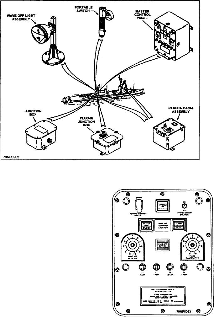
Figure 12-21.--Wave-off light system.
MASTER CONTROL PANEL
The master control panel (fig. 12-22) is located in
the Helicopter Control Station. It controls the power for
the WOL, houses the electronic circuitry which controls
intensity and flash rate of the WOL, permits operation
of the WOL, and indicates which station has control.
REMOTE PANEL ASSEMBLY
The remote panel assembly (fig. 12-23) allows the
WOL to be operated from remote stations located at the
captain's bridge and adjacent to the hanger door.
PLUG-IN JUNCTION BOX ASSEMBLY
Two plug-in junction boxes are contained in one
assembly. The junction boxes are located one on either
side of the hangar door to permit a plug in of a portable
switch to operate the WOL on the flight deck by the
Figure 12-22.--Master control panel.
landing signalman enlisted (LSE).
12-16