
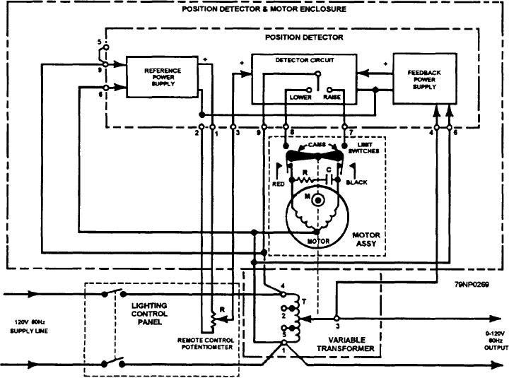
to the lights (fig. 12-28). The transformer wiper
until the feedback voltage equals the reference, and the
motor stops at a position corresponding to the desired
(secondary) is moved by the synchronous motor which
light intensity. Cam-operated limit switches open the
is controlled by the potentiometer in the lighting control
motor circuit and prevent the motor from driving the
panel. The detector circuit in the position detector
wiper on the transformer beyond the upper and lower
determines from the setting of the remote control
stops.
potentiometer whether the motor turns in a direction to
raise or lower the output voltage.
MAINTENANCE REQUIREMENTS
The reference power supply in the position detector
converts ac input voltage to dc, and the potentiometer in
The VLA system contains many electrical and
the control panel determines the magnitude of dc
electronic components which require both preventive
reference voltage sent to the detector circuit. The
and corrective maintenance. The components that we
feedback power supply in the position detector converts
have discussed in this chapter contain many motors,
the ac output voltage from the variable transformer to a
controllers, blowers, heaters, pressure switches, and
proportional dc voltage which is also sent to the detector
lighting fixtures that are exposed to weather. The
circuit.
electronic portions are solid state and are primarily on
The detector circuit consists of a comparator and
printed circuit boards. As an Electrician's Mate you can
solid state switches (TRIACS) which energize either the
realize some of the problems which will be encountered
clockwise (LOWER) or counterclockwise (RAISE)
both with electrical and electronic parts. It is of utmost
windings of the drive motor. The drive motor rotates
importance that you follow all PMS requirements
the wiper shaft on the transformer in the proper direction
carefully to keep all portions of this system operating
Figure 12-28.--Motor-driven remote variable transformer circuit diagram.
12-20