
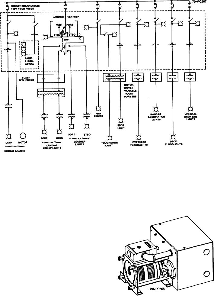
figure 12-26.--Simplified line diagram of the lighting control panel.
which conduct helicopter operations at night. This
2. Line-up lights
control panel is located at the helicopter control station
3. Vertical drop-line lights
and consists of switches, dimmers, and red indicator
lamps. The dimmers are variable autotransformers
4. Edge lights
mounted in the control panel. The lighting control panel
Input power is applied to the variable transformer,
requires input power at 120 volt, 60 Hz and is designed
and the controlled 0- to 120-volt-ac output is connected
to accommodate the applicable light equipment
discussed in the preceding paragraphs. Figure 12-26 is
a simplified line diagram of the lighting control panel.
MOTOR-DRIVEN VARIABLE
TRANSFORMERS
Motor-driven remote variable transformers (fig.
12-27) are used in the VLA lighting control system to
control the intensity of the various lights. There are four
10-ampere and two 22-ampere transformers in the
system. The 22-ampere transformers are used with the
overhead and deck-surface floodlights and the
10-ampere transformers are used with the following
lights:
1. Hangar illumination floodlights
Figure 12-27.--Motor-driven variable transformer.
12-19