operations. These lights give the helicopter pilot a
VERTICAL REPLENISHMENT
visual indication of the ship's heading at all times and
(VERTREP) LIGHTS
provide a height reference during in-flight refueling
VERTREP line-up lights are bidirectional fixtures
operations.
for VERTREP/hover approaches, and they form an
Three HIFR heading lights are installed forward to
athwartship line-up path at approximately 8- to 12-foot
aft on the port side of the ship in a line parallel to the
intervals. Spacing between lights is uniform and such
ship's centerline (heading). Spacing between the lights
that the pilot's view of the lights is not obstructed during
is approximately 20 feet, beginning outside the rotor
the helicopter's approach. When installed in landing
clearance distance and extending forward. All HIFR
areas equipped with landing approach line-up lights, the
heading lights are installed at the same height,
VERTREP line-up lights are connected to the same
approximately 30 to 40 feet above the ship's waterline.
dimmer as the landing approach line-up lights. This
All lights are controlled by a single on/off switch,
switching arrangement prevents the simultaneous
located on the lighting control panel, and area standard
energizing of both the landing approach line-up lights
watertight assembly consisting of a lighting fixture,
and the VERTREP/hover line-up lights.
yellow globe, and a 115-volt, 50-watt rough service
lamp.
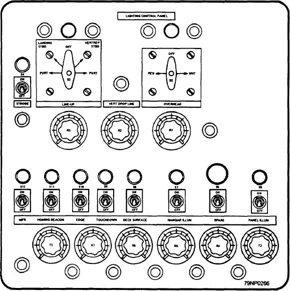
LIGHTING CONTROL PANEL
The lighting control panel (fig. 12-25) that controls
the lights in the VLA package is installed on all ships
Figure 12-25.--Lighting control panel.
12-18

