
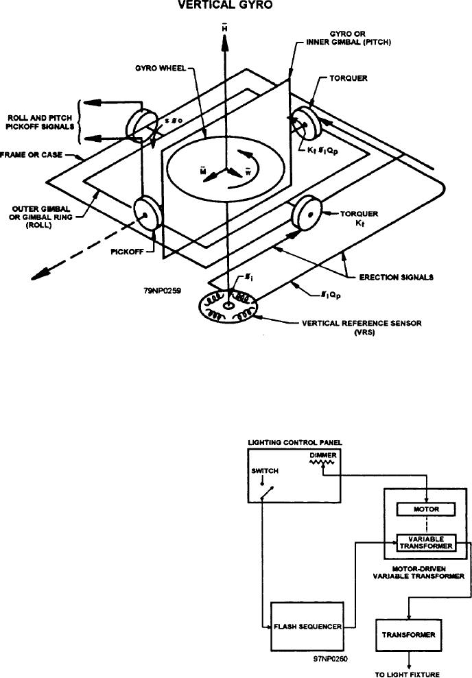
Figure 12-18.--Vertical gyro--line schematic diagram.
a fixed-voltage circuit ( 115 volts), while the lamp ( 150
The primary is connected to a motor-driven, variable
watt) is wired through a step-down transformer ( 115/32
transformer (intensity) and a flash sequencer (fig.
volts) to a variable voltage dimming circuit.
12-19).
EDGE LIGHTS
The edge lights outline the periphery of the
obstruction-free helicopter deck area with a minimum
of four lights along each edge of the area. Edge lights
are red omnidirectional lamps which can be seen in any
direction above deck level. They are connected to the
low voltage side of a 115/12-volt step-down
transformer. The 115-volt side of each transformer (one
transformer per light fixture) is connected to a
motor-driven variable transformer which controls the
intensity of the lights.
LINE-UP LIGHTS
The line-up lights are white and flash in sequence.
They are installed in the deck along the line-up line for
deck landing. Line-up lights are either unidirectional or
bidirectional (LSTs only) dependent on the ship's
landing capability. Each lamp is connected to the
Figure 12-19.--Simplified interconnection of line-up lights.
secondary side of a 115/6.5-volt step-down transformer.
2-13