Home
Download PDF
Order CD-ROM
Order in Print
Figure 12-12.--Hydraulic pump assembly.
Figure 12-15.--Function diagram of the stabilized platform assembly.
Electricians Mate
Page Navigation
434
435
436
437
438
439
440
441
442
443
444
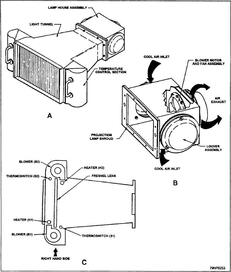
Figure
12-13.--A.
Glide
slope
Indicator;
B.
Lamp
house
assembly;
C.
Temperature
control
section.
12-10