
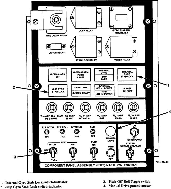
relay) tests and aligns the GSI. Referring to figure 12-8,
signal comes from the linear voltage differential
transformer (LVDT) when the test switch is in the off
you will see the:
position. The core of the LVDT is mechanically
1. internal gyro stab lock,
attached to the hydraulic actuator which levels the
2. the ship's gyro stab lock push button, and
platform. As the actuator moves, the core also moves,
thereby supplying a signal proportional to the amount
3. two test switches
of roll or pitch. These signals can be measured to aid in
As previously mentioned the error signal in the
the maintenance and alignment of the system.
normal mode goes through a stab lock relay. When the
Provisions are also made to manually drive the platform
stab lock button is pushed, the normal error signal
using the test switches and the manual drive
supplied from the gyro is stopped at this point. (See fig.
potentiometer ((4) in fig. 12-8 and may also be seen in
diagram of fig. 12-10).
12-9.) When the stab lock button is pushed, the error
Figure 12-8.--Component panel assembly.
12-6