
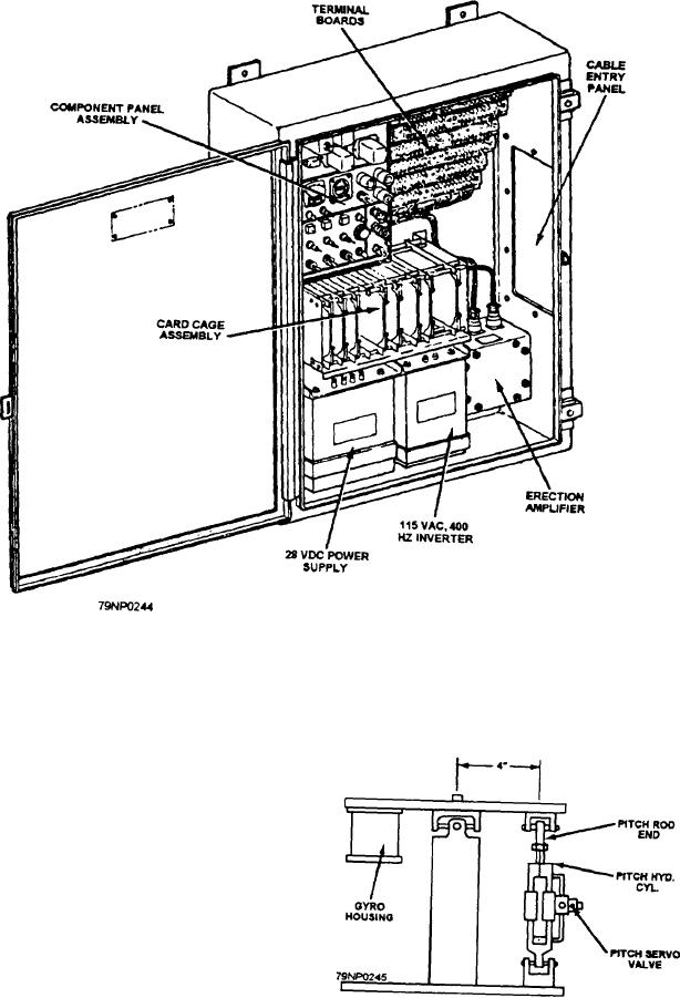
Figure 12-4.--Electronic enclosure assembly.
ELECTRONIC ENCLOSURE
ASSEMBLY
The electronic enclosure assembly (fig. 12-4)
contains the circuits, amplifiers, and other electrical and
electronic components required to control the major
components of the system. To understand the system
operation, it is necessary for you to understand the
operation of the feedback control systems. A feedback
control system compares an input signal with a
reference signal and then generates an error signal. This
error signal is then amplified and used to drive the output
in a direction to reduce the error. This type feedback
system is often referred to as a servo loop. A gyro (fig.
12-5), mounted on the stabilized platform, acts as the
transmitters located on the gimbals in the gyro will sense
Figure 12-5.--Platform pitch drive.
any motion of pitch or roll. As the ship begins to pitch
12-4