2. The light tunnel-- provides space for the focal
length of the lens to be utilized
3. The temperature control section fig.
12-13C)--contains the Fresnel lens which iS
sensitive to temperature
To protect the Fresnel lens from excessive
temperature variations, two heaters, each having a
blower, are mounted on either side of the cell assembly
in the temperature control section. Each heater is
controlled by a thermostat which maintains the
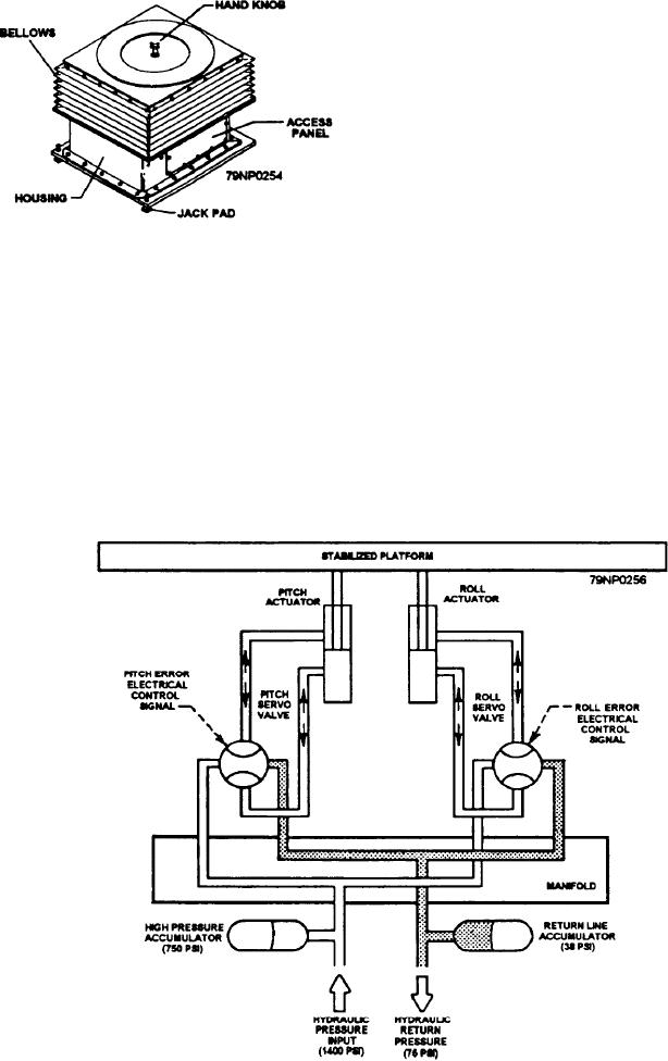
Figure 12-14.--stabilized platform assembly.
temperature at 115F 15 degrees. The blowers
recirculate the heated air throughout the cell assembly.
GLIDE SLOPE INDICATOR (GSl)
STABILIZED PLATFORM
ASSEMBLY
The glide slope indicator (fig. 12-13A) is a cell
The stabilized platform assembly (fig. 12-14),
assembly made up of the following three main sections:
which will remain level despite the pitch and roll attitude
of the ship, provides a mount for the GSI. The assembly,
1. The lamp house assembly (fig. 12-13B)--
shown in figure 12-15, consists of a stabilized platform
contains three source lights, a vent fan to cool
attached to two hydraulic actuators (pitch and roll)
the section, an optical lens (not shown), and
which maintain the platform level at all times. The
Figure 12-15.--Function diagram of the stabilized platform assembly.
12-11

