mount the overload relay on the mounting plate.
Replace the heater coils as the last operat.ion.
Overload relays are PROTECTIVE DEVICES.
After an overload relay has performed its safeguarding
function, you must reset it before running the system
again with overload protection.
REVERSE-POWER RELAY
On all ships with ac ship's service power systems
where the generators are operated in parallel, each
generator control unit has a reverse-power relay. The
approximate] y 10 seconds with reverse power equal to
5 percent of the generator rating.
Reverse-power relays trip the generator circuit
breaker to prevent motoring the generator. This
protection is provided primarily for the prime mover or
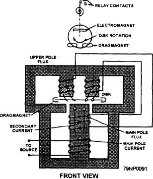
Figure 2-44.--A coil and disk arrangement of an ac
system, rather than for the generator. Motoring results
reverse-power relay.
from a deficiency in the prime mover input to the ac
generator. This deficiency can be caused by loss of or
low steam to the turbine, lack of fuel to the diesel engine
The main relay contacts (not shown in fig. 244) will
or gas turbine, or other factors that affect the operation
safely handle 30 amperes at 250 volts dc and will carry
of the prime mover. In the absence of reverse-power
the current long enough to trip a breaker.
protection, when the input to the generator falls below
The induction disk is rotated by an electromagnet in
that needed to maintain synchronous generator speed,
real power is taken from the ship's service power
the rear of the assembly. Movement of the disk is
damped by a permanent magnet in front of the assembly.
system. The generator acts as a motor driving the prime
mover. Reverse-power protection prevents damage to
The operating torque of the timer element is
the prime mover if a reverse-power condition should
obtained from the electromagnets (fig. 2-44). The
occur.
main-pole coil is energized by the line voltage. This coil
then acts as the primary of a transformer and induces a
The reverse-power relay consists of two induction
voltage in the secondary coil. Current then flows
disk-type elements. The upper element is the timer, and
through the upper pole coils. This produces a torque on
the lower one is the direction element. Figure 2-44
the disk because of the reaction between the fluxes of
shows the coil and induction disk arrangement in the
the upper and lower poles.
induction-type relay timer element. The disk is 4 inches
in diameter and is mounted on a vertical shaft. The shaft
The timer element cannot be energized unless the
power flow is in the direction that will cause tripping.
This interlocking action is accomplished by connection
An arm is clamped to an insulated shaft, which is
of the timer potential coil in series with the contacts of
geared to the disk shaft. The moving contact, a small
the directional element. Thus, the direction of power
silver hemisphere, is fastened on the end of the arm. The
flow controls the timer relay.
electrical connection to the contact is made through the
arm and a spiral spring. One end of the spring is
The directional element is similar to the timing
fastened to the arm and the other end to a slotted
element, except that different quantities are used to
spring-adjusted disk fastened to a molded block
produce rotation of the disk. There is also a different
mounted on the element frame. The stationary contact
contact assembly. The two upper poles of the
is attached to the free end of a leaf spring. The spring
electromagnet are energized by a current that is
is fastened to the molded block, and a setscrew makes
proportional to the line current, and the lower pole is
it possible to adjust the stationary contact position.
energized by a polarizing voltage. The fluxes produced
2-38

