Table 2-8.--Steps to adjust pressure operated switches
ACTION
STEP
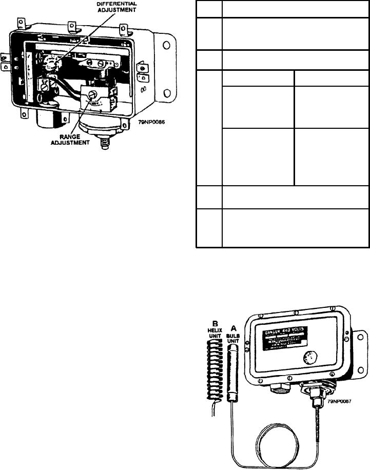
Turn the differential adjustment screw (fig.
1
2-39) counterclockwise against the stop for
minimum differential.
2
Bring the system pressure to that at which
you wish the switch to close.
THEN
IF
3
Turn the range screw
Contacts are open
slowly clockwise
when the desired
until the contacts just
temperature is
close.
reached.
Turn the range screw
Contacts are closed
slowly
when the desired
counterclockwise
temperature is
until the contacts
reached.
Figure 2-39.--A pressure-operated switch.
open; then clockwise
until they just close.
the same regardless of the kind of pilot device
4
Bring the system to the pressure at which
you wish the switch to open.
used to control the circuit. To maintain more or
less constant temperature or pressure, switch
Turn the differential adjustment screw
5
slowly clockwise to widen the differential
contacts are arranged to close when the pressure
until the desired opening pressure is
or temperature drops to a predetermined value
obtained.
and to open when the pressure or temperature
rises to the desired value. The reverse action
Thermal Unit Type
can be obtained by a change in the contact
positions.
The bulb and helix units can be connected to the
The difference in pressure for contact opening and
switch section (fig. 2-40). The bulb unit (fig. 2-40, view
closing is the differential. The switch mechanism has a
built-in differential adjustment so that the differential
can be varied over a small range. Once set, the
differential remains essential y constant at all pressure
settings.
Each switch has a range adjustment that sets
the point at which the circuit is closed. Changing
the range adjustment raises or lowers both the
closing and opening points without changing the
differential.
Adjustments
The following table describes the steps in adjusting
pressure operated switches (table 2-8);
Figure 2-40.--Thermal units.
2-33

