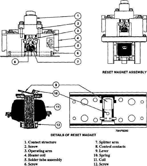
Figure 2-43.--An adjustable thermal overload relay and a reset magnet assembly.
The adjustable thermal relay may be adjusted to trip
have reset magnet assemblies attached. You may have
at a value between 90 to 110 percent of the rated coil
to replace the heater coils from the relay. If so, remove
current. To change the operating point, loosen the
the four screws that hold the overload relay to the
binding screws that hold the relay heater coil (4) so that
mounting plate. When removing the relay from the
the coil position may be changed. Moving the coil away
mounting plate, use care not to lose the phenolic pin and
from the relay will increase the amount of current
bearing block located between the thermal blocks on the
needed to trip the relay. Moving the coil closer to the
underside of the relay.
relay will decrease the current needed to trip the relay.
This range of adjustment is available only within the
Next, remove the four large countersunk screws that
range of 90 to 110 percent of coil rating. Each rating
hold the mounting plate and the reset magnet assembly
has a different manufacture part number. The correct
to the square posts. Remove the four screws in the
rating is installed when the controller is installed in the
mounting plate, which support the reset magnet. Take
ship. Do not use another rating. Make sure both heater
care not to loosen the lever and spring (9 and 10).
coils in each overload relay are the same rating.
Remove the two screws (12) and pull the plunger guides.
Remove the old coil (11) and install the new coil. Then
The terminal plates and the underside of the slotted
insert the plunger guides and replace the screws (12).
brackets of the heater coil assembly are serrated so that
Reassemble the magnet, spring, and lever to the
the coil is securely held in position when the binding
screws are tightened. Some thermal overload relays
mounting plate. Mount the plate on the posts, and then
2-37

