If one generator fails, the voltage output of that
generator will drop. When the voltage drops below the
terminal voltage of the bus to which it is connected, the
generator terminal current (through the relay series coil)
will reverse. However, the polarity of the voltage
applied to the potential coil remains the same. When the
reversed current exceeds the calibration setting of the
relays, the armature rotates, and through a mechanical
linkage, trips the circuit breaker that opens the bus. This
action disconnects the generator from the line.
PHASE-FAILURE RELAY
Because the propulsion type of ac motors require
full voltage and current from all three phases supplied
by the generator, phase-failure protection is a
requirement for this type of shipboard propulsion.
This type of relay is used to detect short circuits on
alternating current propulsion systems for ships.
Ordinary instantaneous trip relays cannot be used
because, under certain conditions, when the motor is
plugged, the momentary current may be as great as the
short-circuit current.
The relay in use operates when there is a current
unbalance. It is connected in the control circuit so that
it will shutdown the system fault. However, operation
of the relay is not limited to short-circuit detection. The
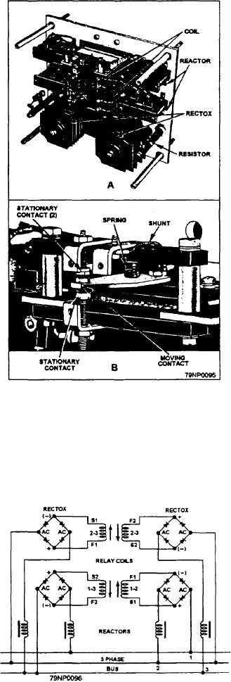
relay may be used as a phase-failure relay. Figure 2-48
Figure 2-48.--A phase-failure day.
shows a phase-failure relay. View A is the arrangement
of the parts in the complete assembly, and view B is a
closeup of the contact assembly. The entire unit is
are not directly connected to the bus lines. Instead,
enclosed in a cover to prevent dirt and dust from
connection is made through the Rectox units, which are
interfering with its operation.
connected to the line in series with a reactor.
The moving contact is the only moving element in
the complete relay. There are two stationary contacts
that make it possible to have the relay open or close a
circuit when it operates.
Two coils are built into the relay. Each coil has two
windings that are actuated by direct current from the two
Rectox units. Four reactors are used to get sensitivity
over a wide frequency range, Because variations in
reactance are introduced during manufacture, two
resistors are provided to balance the systems during the
initial adjustment.
Figure 2-49 is a schematic wiring diagram of a
phase-failure relay. The windings are identified by
numbers that refer to numbered leads in the three-phase
bus. Winding 1-3 is connected to lines 1 and 3; winding
1-2 is connected to lines 1 and 2; and the two windings
Figure 2-19.--Schematic wiring of a phase-failure relay.
2-3 are connected to lines 2 and 3. However, the coils
2-41

