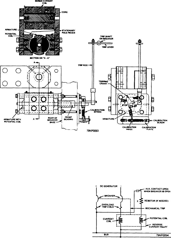
Figure 2-46.--Mechanical construction of an dc reverse-current relay.
shown in figure 2-46. Note that the construction is
spring tends to hold the tripping crank on the armature
shaft against a fixed stop. This pressure is maintained
similar to that of a bipolar motor with stationary pole
as long as current flows through the line in the right
pieces and a rotating armature.
direction.
Figure 2-47 shows the connections of a dc
reverse-current relay. The potential coil is wound on the
armature, and a current coil is wound on the stationary
pole pieces. When used as a protective device, the
current coil is in series with the load, and the potential
coil is connected across the line. If the line voltage
exceeds the value for which the potential coil is
designed, connect a dropping resistor at point X in the
circuit.
When the line is energized, current flowing through
the series coil produces a magnetic field across the air
gap. Voltage applied to the armature winding produces
a current in the armature coil, which interacts with the
magnetic field. A torque is developed that tends to rotate
the armature in a given direction. The construction of
the relay is such that the armature cannot turn through
360 degrees as in a motor. Instead, the torque produced
Figure 2-47.--A dc reverse-current connection.
by the two fields plus the force from the calibrated
2-40

