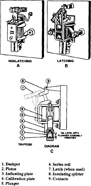
The operating (series) coil (6) is connected in series
turned Then, to lower the tripping current, raise the
with the protected circuit. Therefore, the load current
dashpot by turning it. This action raises the plunger
flows through the coil. If the circuit current rises above
further into the magnetic circuit of the relay so that a
normal because of overload conditions, it will cause an
lower current will trip the relay.
increase in the magnetic lines of flux about the coil. The
You can increase the current at which the relay trips
increased flux lifts the iron plunger (5) into the center
by turning the dashpot in a reverse direction. This action
of the coil and opens the contactor/contacts (9). This,
reduces the magnetic pull on the plunger and requires
in turn, causes the main contactor (not shown) to open,
and disconnects the motor or other device from the line.
more current to trip the relay. After the desired settings
An oil dashpot mechanism (1 and 2) is used to prevent
have been obtained, lower the indicating plate over the
the operation of the relay on motor starting current
hexagonal portion of the dashpot to again indicate the
surges.
tripping current and lock the dashpot in position.
If the relay does not have manual latching, a
Figure 2-42 shows two magnetic types of ac
three-wire control is provided to give automatic reset
overload relays. View A is the nonlatching type, and
after an overload occurs. The manual-latch relay is
view B is the latching type. In view C the various
generally used with two-wire control. The latch (7)
components are identified
holds the contacts in the open position after an overload
has occurred and the circuits have been de-energized.
The operator must manually reset the overload relay at
the controller.
THERMAL OVERLOAD RELAY
The thermal type of overload relay (ac and dc) is
designed to open a circuit when excessive current causes
the heater coils to reach the temperature at which the
ratchet mechanism releases. The heater coils are rated
so that normal circuit current will not produce enough
heat to release the ratchet mechanism.
The essential operating parts of a de thermal
overload relay (fig. 2-43) are the two heater coils (4),
two solder tube assemblies (5), and control contacts (8).
Under normal conditions the splitter arm (7) (so called
because it splits the overload contacts) completes a
circuit with the contacts. The spring is then under
compression, and the operating arm (3) tends to rotate
the splitter arm out of the circuit. This action is
prevented by the ratchet assembly, which is held by the
solder film between the outer and inner part of the solder
tubes.
When current flows through the heater coils and
produces enough heat to melt the solder film, the inner
part of the solder tube assembly rotates and releases the
ratchet mechanism to open the control circuits. When
this happens, the circuit to the coil handling the power
contacts (not shown in fig. 2-43) opens and disconnects
the load. As soon as the load is disconnected, the heaters
cool, and the solder film hardens. When the hardening
is complete, the relay is ready to be reset with the reset
Figure 2-42.--Two ac overload relays.
button.
2-36

