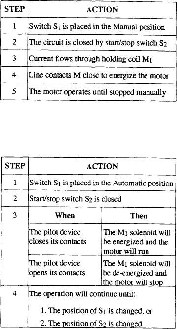
Table 2-9.--Manual Operation of Pilot Control Circuit
A) is normally used when liquid temperatures are to be
controlled. However, it may control air or gas
temperatures, provided the circulation around it is rapid
and the temperature changes at a slow rate.
The helical unit (fig. 2-40, view B) has been
specifically y designed for air and gas temperature control
circuits. To be most effective, the thermal unit must be
located at a point of unrestricted circulation so it can
"feel" the average temperature of the substance that is
to be controlled.
Some switches are stamped WIDE DIF-
FERENTIAL. They are adjusted in the same manner
The following table describes the sequence of
described for the regular controls. However, because of
events during the automatic operation of the circuit in
slight design changes, it is possible to get wider variation
table 2-10.
in differential settings.
Table 2-10.--Automatic Operation of Pilot Control Circuit
Maintenance
When adjusting temperature controls, allow several
minutes for the thermal unit to reach the temperatures
of the surrounding air, gas, or liquid before setting the
operating adjustments. After adjusting the operating
range of pressure or temperature controls, check the
operation through at least one complete cycle. If you
find variation from the desired operating values, go
through the entire procedure again and observe
operation through a complete cycle.
PILOT CONTROL DEVICES
A pilot is defined as a director or guide of another
thing (or person). You may be familiar with ship pilots,
pilot rudders, and pilot flames. In this text, a pilot is a
small device that controls a relative] y larger device or
mechanism, usually doing so by electrical means. The
previously described float switch and pressure-operated
switches are representative examples of such pilot
devices. Pilot devices are limited in their ability to
handle large currents and voltage required to operate
PROTECTIVE DEVICES
shipboard motors or power-handling units. Therefore,
Protective devices allow normal operation of
it is customary for a pilot device to actuate only a
circuits to continue unhampered. Once something goes
magnetic switch. The magnetic switch can be chosen
wrong in the circuit, protective devices will de-energize
with characteristics suitable for handling the desired
the circuit to minimize of prevent damage to equipment
amount of power in the motor circuit.
and ensure the safety of personnel. A thorough
knowledge of protective devices will help you isolate
Float switches used as pilot devices control the
troubles in circuits, find the cause of interruption, clear
pump operation through other controls. A typical
the trouble, and restore operation with minimum loss of
control circuit is shown in figure 2-38.
time.
Switch S 1 makes it possible to have either manual
or automatic operation of the motor-driven device.
MAGNETIC OVERLOAD RELAY
Table 2-9 describes the sequence of events when
A magnetic type of overload relay for a dc system
operating the pilot device control circuit (table 2-10)
is shown in figure 2-41. A pictorial view and a diagram
manually.
2-34

